Closed loop brain machine interface

a closed loop, brain machine technology, applied in the field of interfaces, can solve problems such as paralysis of patients, no longer voluntarily activating muscles, and encountering a number of technical difficulties

Inactive Publication Date: 2007-04-24
DUKE UNIV
View PDF72 Cites 145 Cited by
  • Summary
  • Abstract
  • Description
  • Claims
  • Application Information

AI Technical Summary

Benefits of technology

[0015]A real time closed loop brain-machine interface is disclosed. In a preferred embodiment, the real time closed loop brain-machine interface comprises: (a) a plurality of electrodes adapted to be chronically implanted in the nervous system of a subject and to acquire extracellular electrical signals from a population of individual neural cells; (b) a signal processing mechanism adapted to form extracted motor commands from the extracellular electrical signals, the signal processing mechanism adapted to communicate with the plurality of electrodes; and (c) an actuator adapted to respond t...

Problems solved by technology

As a result, the patient is paralyzed, and can no longer voluntarily activate muscles that are innervated by regions of the spinal cord below the level of the injury.
Earlier attempts to utilize signals recorded directly from neurons for the express purpose of controlling an external actuator have, however, encountered a number of technical difficulties.
One problem is how to obtain stable electrical signals of sufficient amplitude and temporal resolution for real-time control of an external device.
Previous approaches have been used, but have been unsuccessful in this regard.
The use of the signals recorded in the second approach, however, presents a major problem for actuator control.
Thus, averaging must be used over many movement attempts to extract a usable signal and the extracted signal cannot be employed to reproduce a time-varying arm trajectory.
For this reason, this approach is less than desirable and perhaps not useful for real-time neural...

Method used


Image

  • Closed loop brain machine interface
  • Closed loop brain machine interface
  • Closed loop brain machine interface

Examples


example 1

LABORATORY EXAMPLE 1

Implantation of Microwire Arrays

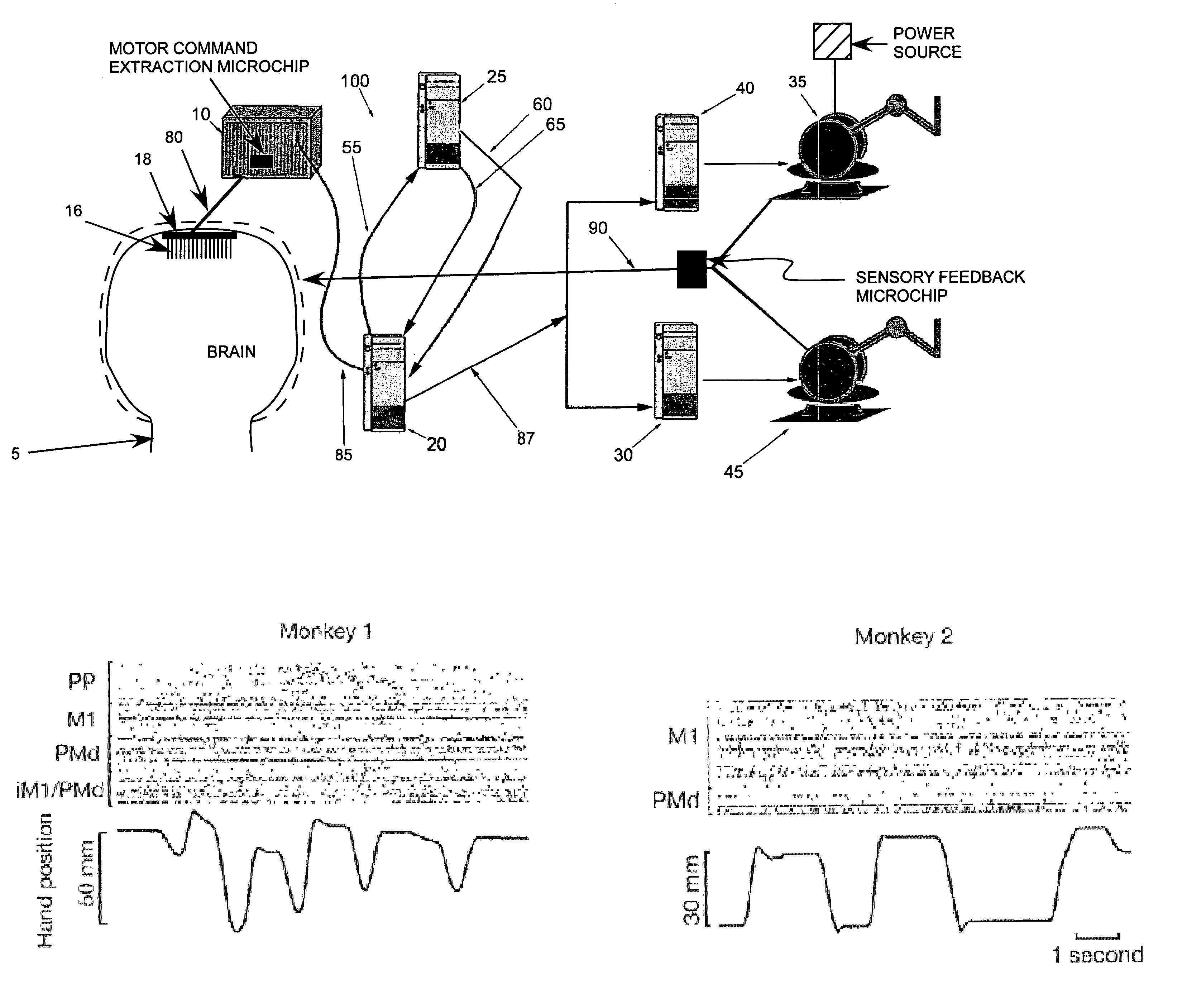
[0243]Microwire arrays were implanted in multiple cortical areas of two owl monkeys (Aotus trivirgatus) (Nicolelis et al., (1998) Nature Neurosci. 1: 621–630; Laubach et al., (2000) Nature 405: 567–571; Nicolelis et al., (1997) Neuron 18: 529–537). In the first monkey, 96 microwires were implanted in the left dorsal premotor cortex (PMd, 16 wires), left primary motor cortex (MI 16) (Stepniewska et al., (1993) J. Comp. Neurol. 330: 238–271; Preuss et al., (1996) J. Comp. Neurol. 371: 649–676), left posterior parietal cortex (PP, 16) right PMd and MI (32) andd right PP cortex (16). In the second monkey, 32 microwires were implanted in the left PMd (16) and in the left MI (16).

example 2

LABORATORY EXAMPLE 2

Recording of Cortical Neural Ensembles

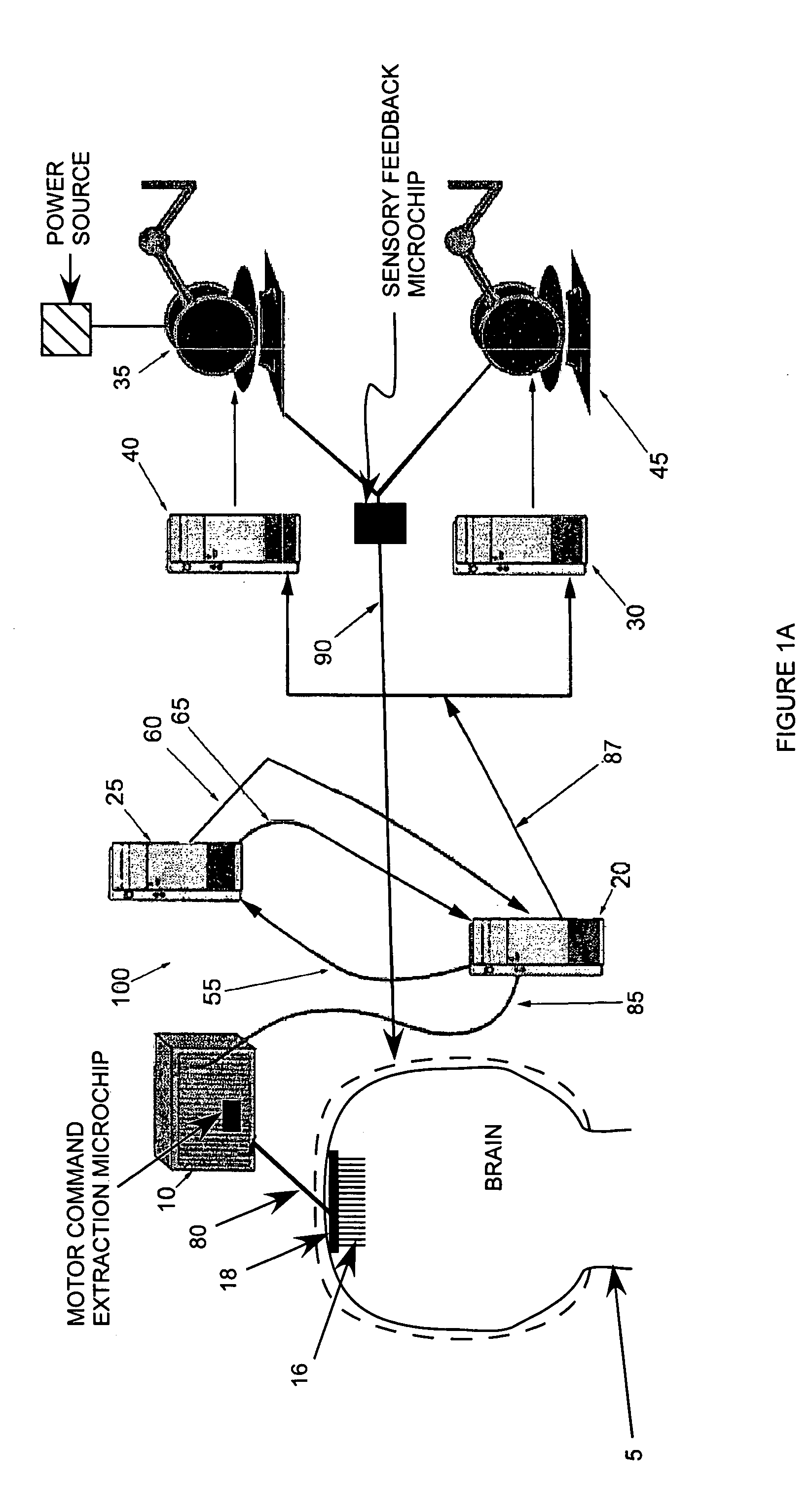
[0244]Recordings of cortical neural ensembles began 1–2 weeks after the implantation surgery and continued for 12 months in monkey 1, and 24 months in monkey 2. During this period, the monkeys were trained in two distinct motor tasks. In task 1, animals made one-dimensional (1-D) hand movements to displace a manipulandum in one of two directions (left vs. right) following a visual cue. In task 2, the monkeys made three-dimensional (3-D) hand movements to reach for small pieces of food randomly placed at four different positions on a tray. Cortical recordings were obtained while the two subjects were trained and tested on both tasks (FIG. 1A).

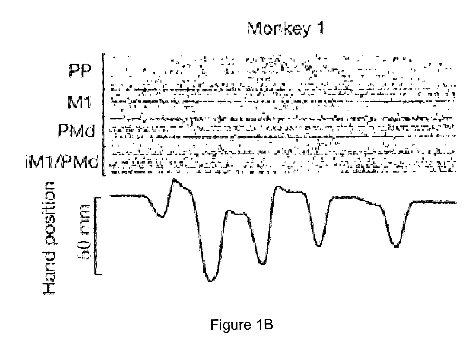
[0245]FIGS. 1B–1C illustrate samples of the raw neuronal data obtained while the animals performed task 1. In both monkeys, coherence analysis (Brillinger, (1981) Time Series. Data Analysis and Theory, Holden-Day, San Francisco, Calif.; Bendat & Piersol, (1986) Random Data. Analysis and M...

example 3

LABORATORY EXAMPLE 3

Application of Algorithms

[0246]It was then investigated whether both linear (Brillinger, (1981) Time Series. Data Analysis and Theory, Holden-Day, San Francisco, Calif.; Bendat & Piersol, (1986) Random Data. Analysis and Measurement Procedures, Wiley, New York, N.Y.; Halliday et al., (1995) Prog. Biophys. Mol. Biol. 64: 237–278) and artificial neural network (ANN) (Powell, (1977) Math. Program. 12: 241–254; Ghazanfar et al., (2000) J. Neurosci. 20: 3761–3775) algorithms could be used to predict hand position in real-time. For 1-D movements, it was observed that both algorithms yielded highly significant real-time predictions in both monkeys (FIGS. 2C–2D). These results were obtained in spite of the fact that the trajectories were quite complex, involving different starting positions, as well as movements at different velocities. For example, in the session represented in FIG. 2C, the activity of 27 PMd, 26 MI, 28 PP, and 19 ipsilateral MI / PMd neurons in monkey 1 ...


PUM


Abstract

A closed loop brain-machine interface is disclosed. The closed loop brain-machine interface translates one or more neural signals into a movement, or a series of movements, performed by a machine. The close-loop brain-machine interface also provides sensory feedback to the subject. Methods of employing the closed loop brain-machine interface are also disclosed.

Description

GOVERNMENT RIGHTS[0001]This invention was made with Government support under contract 313-4073 awarded by DARPA and grants R01-NS40543 and N01-NS62352, awarded by NIH. Therefore, the Government has certain rights in this invention.TECHNICAL FIELD[0002]The present invention relates generally to an interface between a machine and a patient's brain, and more particularly to an interface between one or more types of neural signals originating in the brain of a patient. The signals are transmitted to a responsive mechanical device, which, in turn, relays sensory feedback to the patient. The present invention further generally relates to methods by which one or more neural signals originating in a subject's brain are converted to motion in a mechanical device.[0003]AbbreviationsANNartificial neural networkDSPdigital signal processingEEGelectroencephalographfMRIfunctional magnetic resonanceimagingLANlocal area networkM1primary motor cortexMNAPmany neuron acquisition processorPMddorsal prem...

Claims


Application Information

Patent Timeline
IPC IPC(8): A61N1/36A61B5/375A61F2/70G06F3/00G06F3/01G06F17/00
CPCA61B5/0478A61B5/72G06F3/015G06F3/016A61B5/0482A61B5/1114A61B5/6868A61B5/7221A61B5/7455A61B2503/40A61B2503/42A61B2562/0209A61B2562/046A61F2/72A61F2002/704Y10S128/905A61B5/375A61B5/291A61B5/293
Inventor NICOLELIS, MIGUEL A. L.CHAPIN, JOHN K.WESSBERG, JOHAN
Owner DUKE UNIV
Why Eureka
Try Eureka