Electrical junction box template and method of use

a junction box and template technology, applied in the field of electric junction box template and method of use, to achieve the effect of accurately locating openings

Inactive Publication Date: 2007-05-01
BREE AARON
View PDF16 Cites 20 Cited by
  • Summary
  • Abstract
  • Description
  • Claims
  • Application Information

AI Technical Summary

Benefits of technology

[0002]The present invention is directed to a device and method for accurately locating openings in wall surfaces for electrical junction boxes. Two embodiments of the present invention are directed to p

Problems solved by technology

A recurring problem for do-it-yourself homeowners and professional contractors is accurately locating a hole for the electrical junction box that is both square and level.

Method used


Image

  • Electrical junction box template and method of use
  • Electrical junction box template and method of use
  • Electrical junction box template and method of use

Examples


first embodiment

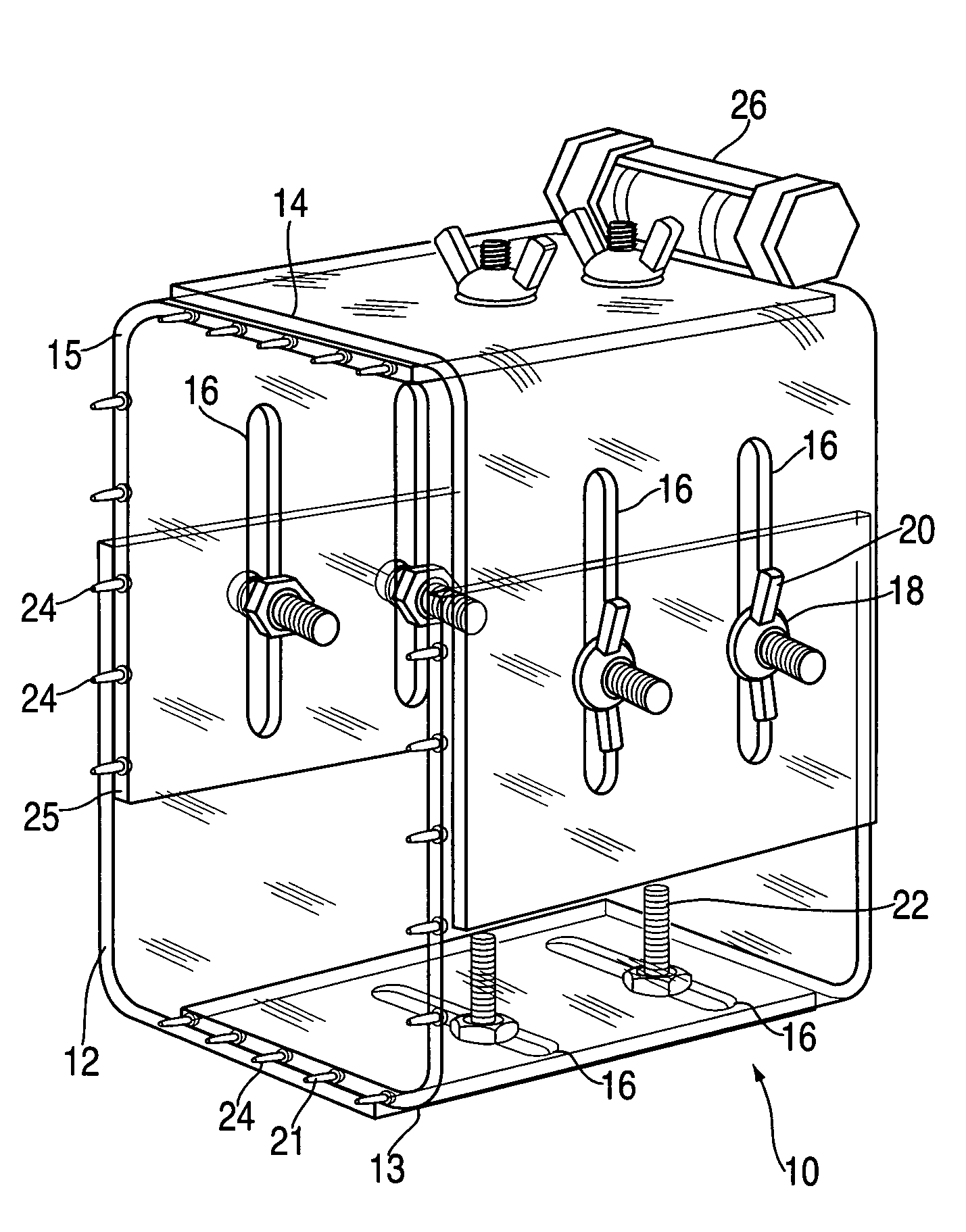
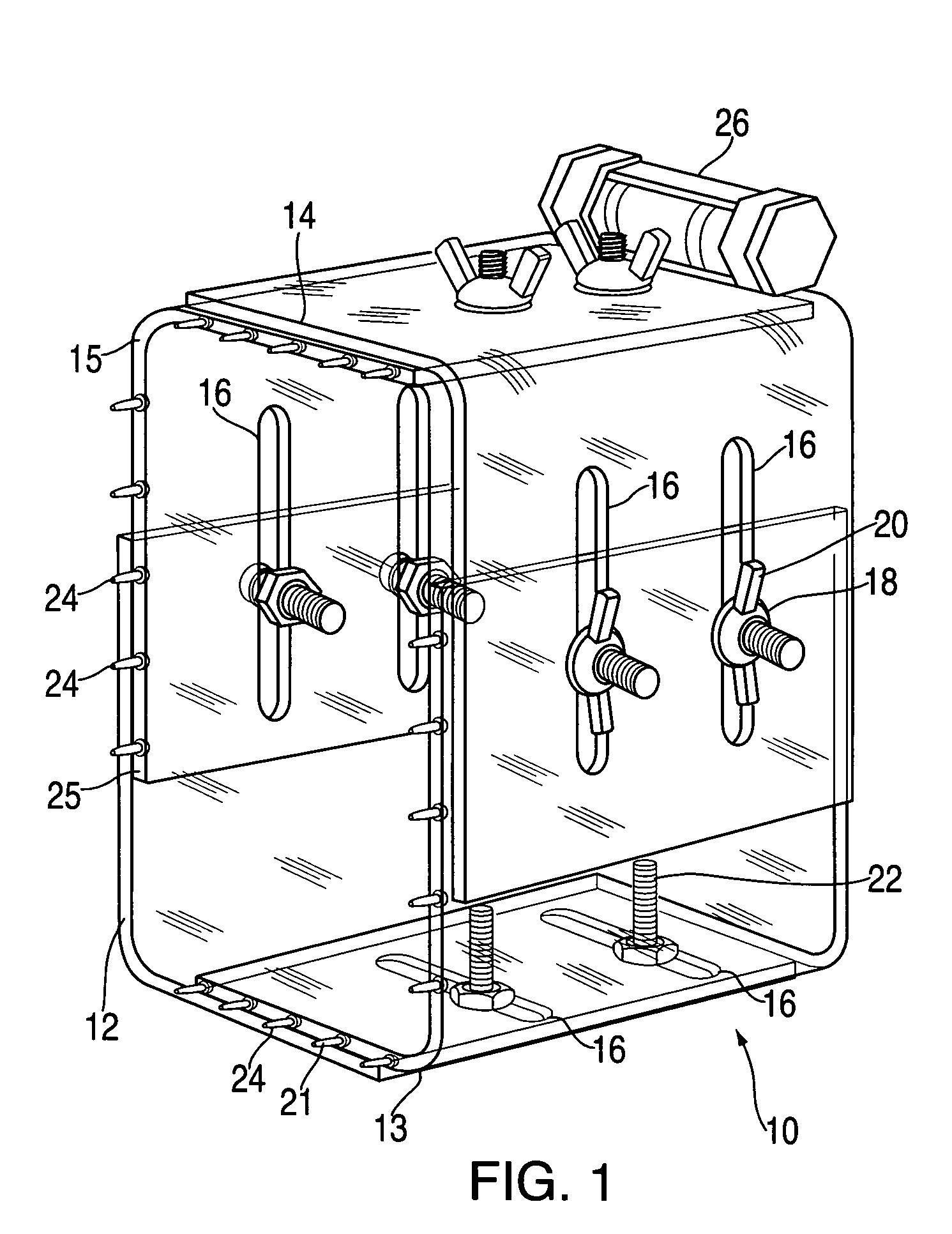
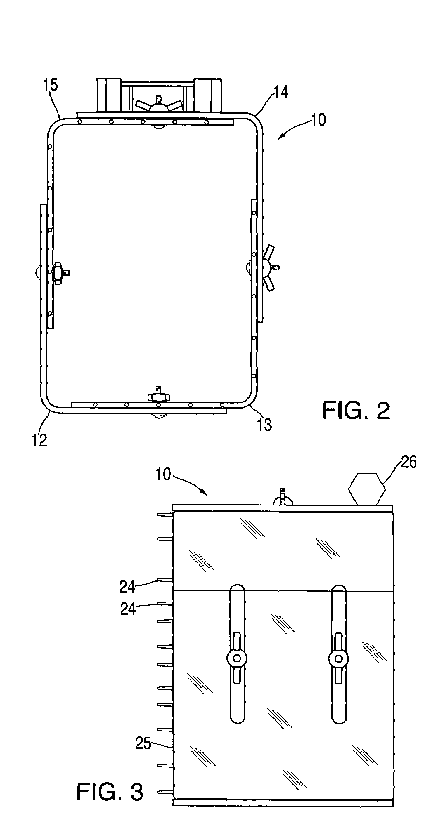
[0011]FIGS. 1 to 4 illustrate the present invention. A hollow box 10 comprises two mating half rectangular shells 12 and 14. As described below, the box 10 can be adjusted in size to match the size of an electrical junction box. The shells each comprise a plurality of slots 16. The four mating shells 12, 13, 14 and 15 are connected by a plurality of fasteners 18 through the corresponding slots 16. The fasteners 18 illustrated in FIG. 1 are conventional wing nuts 20 and bolts 22 but those of ordinary skill in the art will recognize that other similar fastening devices may be used.

[0012]In the embodiment shown in FIG. 1, the size and shape of the box 10 can be adjusted by loosening the bolts and screws and sliding the mating shells 12 and 14 relative to each other until the desired size of the electrical junction box to be installed in the wall is achieved.

[0013]The box 10 further comprises a plurality of sharp and generally stiff projections 24 on its back surface 25. As described be...

third embodiment

[0017]The third embodiment illustrated in FIGS. 6 and 7 is directed to creating junction box openings when the sheetrock is first installed to create the walls. The prior two embodiments are generally directed for use on previously installed walls for the addition of junction boxes.

[0018]FIG. 6 illustrates add-on clips 100. The clips 100 are formed from stiff metal and attached to a junction box 101 prior to installation of the sheetrock walls. The clips comprise a base 102 for sliding attachment to the junction box and sharp protrusions 104. The shape of the base 102 creates an adjustable tension so the clip 100 stays in place and can be adjusted to different wall thicknesses. As is normal in new construction, the junction box 101 is attached to wall studs 106. The sheetrock 108 is then attached to the stud 106. The sharp protrusions 104 will protrude through the front surface of the sheetrock 108 allowing the opening for the junction box 106 to be accurately located and cut out. O...


PUM


Abstract

A device and method for accurately locating electrical junction box openings in sheetrock walls is disclosed. The various embodiments disclosed means for predetermining the shape of the hole to be cut in the wall to locate the electrical junction box and then to place the appropriate hole in the wall.

Description

BACKGROUND OF THE INVENTION[0001]The present invention is directed to the field of devices used to create cutouts in sheetrock walls for electrical devices and junction boxes. A recurring problem for do-it-yourself homeowners and professional contractors is accurately locating a hole for the electrical junction box that is both square and level. The present invention in its various embodiments, solves this problem in a simple and accurate fashion.SUMMARY OF THE INVENTION[0002]The present invention is directed to a device and method for accurately locating openings in wall surfaces for electrical junction boxes. Two embodiments of the present invention are directed to placing cut-outs in existing walls while the third embodiment is directed to construction of new walls. The present invention is also directed to a method of using the device to create cut-outs in walls.BRIEF DESCRIPTION OF THE DRAWINGS[0003]FIG. 1 is a plan view of an embodiment of the present invention.[0004]FIG. 2 is...

Claims


Application Information

Patent Timeline
IPC IPC(8): G01B5/14G01B3/14
CPCB25H7/04H02G3/00H02G3/12H02G2200/30Y10S33/10
Inventor BREE, AARON
Owner BREE AARON
Why Eureka
Try Eureka