Low profile gas burner for a cooking appliance

Inactive Publication Date: 2007-05-01
MAYTAG
View PDF5 Cites 5 Cited by
  • Summary
  • Abstract
  • Description
  • Claims
  • Application Information

AI Technical Summary

Benefits of technology

[0007]The present invention is directed to a cooking appliance including a low profile gas burner assembly. In accordance with a preferred embodiment of the invention, the cooking appliance includes a cabinet, first and second oven cavities arranged within the cabinet, and at least one gas burner assembly positioned within each of the first and second oven cavities. More specifically, the gas burner assembly includes a first end, defining an inlet portion, interconnected with a second end, defining an outlet portion having arranged thereon a plurality of gas discharge ports, through an intermediate portion. The gas burner assembly is formed from a tubular member having a defined diameter. In general, the intermediate portion maintains a distance up to several times the diameter of the tubular member between t

Problems solved by technology

In any event, oven designs require sufficient space to accommodate one or more gas burner assemblies.
Unfortunately, while effective at eliminating adverse effects of the reverse density driven flow, the space between the inlet and outlet means that more space is needed for the burner assembly which, in turn, disadvantageously results in a reduction in oven cavity size.
This is especially true in dual oven ranges wherein the space required to accommodate multiple gas burner assemblies in two oven cavities reduces the overall space available within each oven cavity.

Method used


Image

  • Low profile gas burner for a cooking appliance
  • Low profile gas burner for a cooking appliance
  • Low profile gas burner for a cooking appliance

Examples


Embodiment Construction

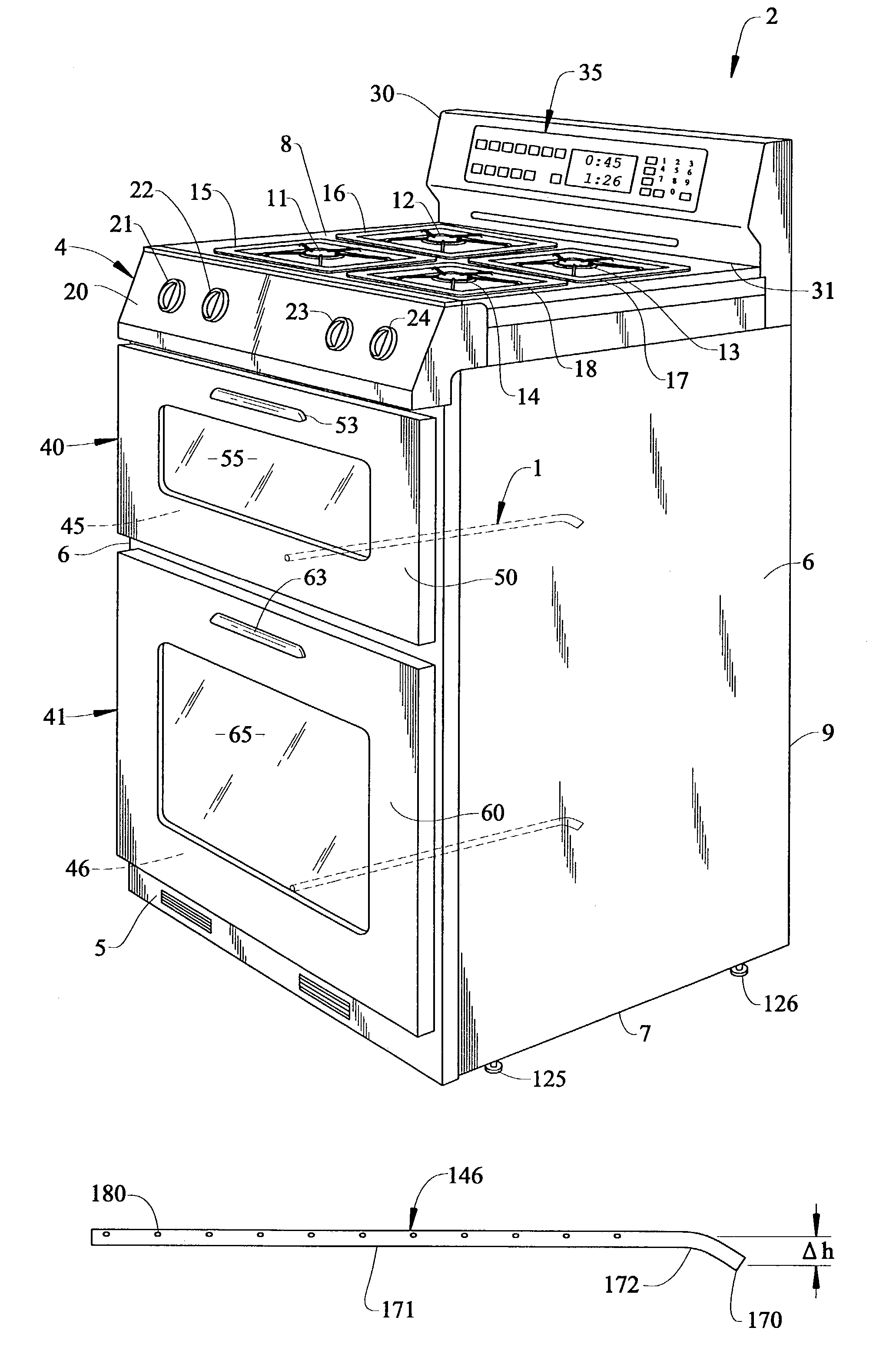
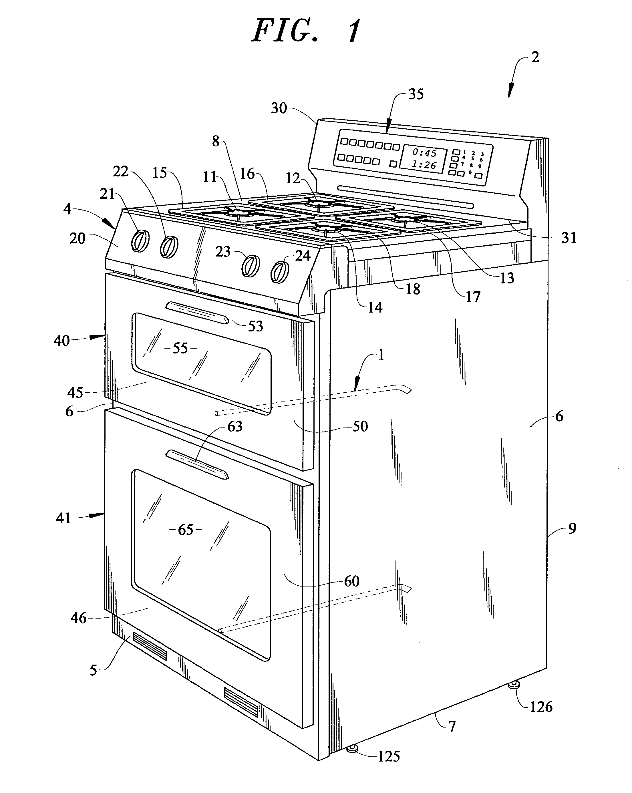
[0013]With initial reference to FIG. 1, a low profile gas burner arrangement 1 constructed in accordance with the present invention is shown incorporated into a cooking appliance generally indicated at 2. As shown cooking appliance 2 takes the form of a free-standing gas range unit. Cooking appliance or range 2 includes a cabinet 4 having a front panel portion 5, side panel portion 6, bottom portion 7, a range top 8 and main back panel 9. In a manner known in the art, range top 8 can take on various forms. Specifically, in the embodiment shown, range top 8 is shown as a gas cooktop incorporating various gas burner elements 11–14, and associated burner grates 15–18. As shown, range 2 further includes a front control surface 20 which preferably supports a plurality of control knobs 21–24 for controlling the activation / de-activation of gas burners 11–14 respectively. Furthermore, range 2 includes a rear, upstanding control panel 30 arranged at an upper rear portion of cabinet 4. In the...


PUM


Abstract

A gas cooking appliance includes a low profile gas burner assembly positioned within an oven cavity. The low profile gas burner assembly, formed from a tubular member having a defined diameter, includes a first end, defining an inlet portion, interconnected with a second end, defining an outlet portion, through an intermediate portion. In accordance with the invention, the intermediate portion maintains a vertically spaced relationship between the inlet portion and outlet portion from about 1.0 to 3.33 times the diameter of the tubular member, preferably about 1.33 to 2.66 times the diameter and, most preferably, approximately twice the diameter of the tubular member.

Description

BACKGROUND OF THE INVENTION[0001]1. Field of the Invention[0002]The present invention pertains to the art of cooking appliances and, more particularly, to a cooking appliance incorporating a low profile gas burner assembly.[0003]2. Discussion of the Prior Art[0004]In general, it is known to utilize gas as a heat source in a cooking appliance. Typically, the gas heat source is in the form of a gas burner assembly located at a bottom portion of an oven cavity, either out in the open or, below a false bottom panel. In some cases, another gas burner assembly is positioned in an upper portion of the oven cavity for broiling operations. In any event, oven designs require sufficient space to accommodate one or more gas burner assemblies.[0005]Conventionally, oven cavities are designed with a considerable amount of space allocated for the gas burner assembly. In a manner known in the art, inlet and outlet portions of the gas burner assembly are maintained in a well defined spaced relationsh...

Claims


Application Information

Patent Timeline
IPC IPC(8): F24C15/00F24C15/32F24C3/08
CPCF24C3/087
Inventor BARNES, SHELTON T.BROCK, EDDIE MAXLARSEN, CHRISTOPHER A.PLACE, GERALD R.
Owner MAYTAG
Why Eureka
Try Eureka