Low profile acoustic flooring

a low-profile, acoustic flooring technology, applied in the direction of shock absorbers, machine supports, building scaffolds, etc., can solve the problems of laborious, time-consuming, and difficult installation of acoustic floors, and achieve the effect of reducing the step height of an acoustic floor, facilitating the leveling of the acoustic floor, and substantially reducing the step siz

Active Publication Date: 2007-05-01
ETS-LINDGREN
View PDF31 Cites 55 Cited by
  • Summary
  • Abstract
  • Description
  • Claims
  • Application Information

AI Technical Summary

Benefits of technology

[0008]The present invention provides a method for mounting an acoustic structure upon a host surface that reduces the step height of an acoustic floor and enables easy leveling of the acoustic floor. According to the present invention, an acoustic isolator is partially but substantially recessed within the acoustic floor so that only a bottommost portion of the isolator extends below the acoustic floor to make contact with the host floor. Because the acoustic isolator is recessed substantially within the acoustic floor, the step size is substantially reduced. Thus, the isolator provides acoustic isolation between the host floor and the acoustic floor without substantially increasing the height of the acoustic floor above the host floor.
[0009]According to another aspect of the invention, a leveling mechanism is provided that enables leveling of the floor from above with the floor in place. The leveling mechanism is also substantially or totally recessed within the body of the acoustic floor. Access is provided to the leveling mechanism from above to enable in-place leveling of the acoustic floor. In this way leveling adjustments can be made without removing the floor or any part thereof.

Problems solved by technology

This results in considerable difficulty installing the acoustic floor because the acoustic floor must be leveled.
As can be imagined, this can be a laborious, time-consuming task.

Method used


Image

  • Low profile acoustic flooring
  • Low profile acoustic flooring
  • Low profile acoustic flooring

Examples


Embodiment Construction

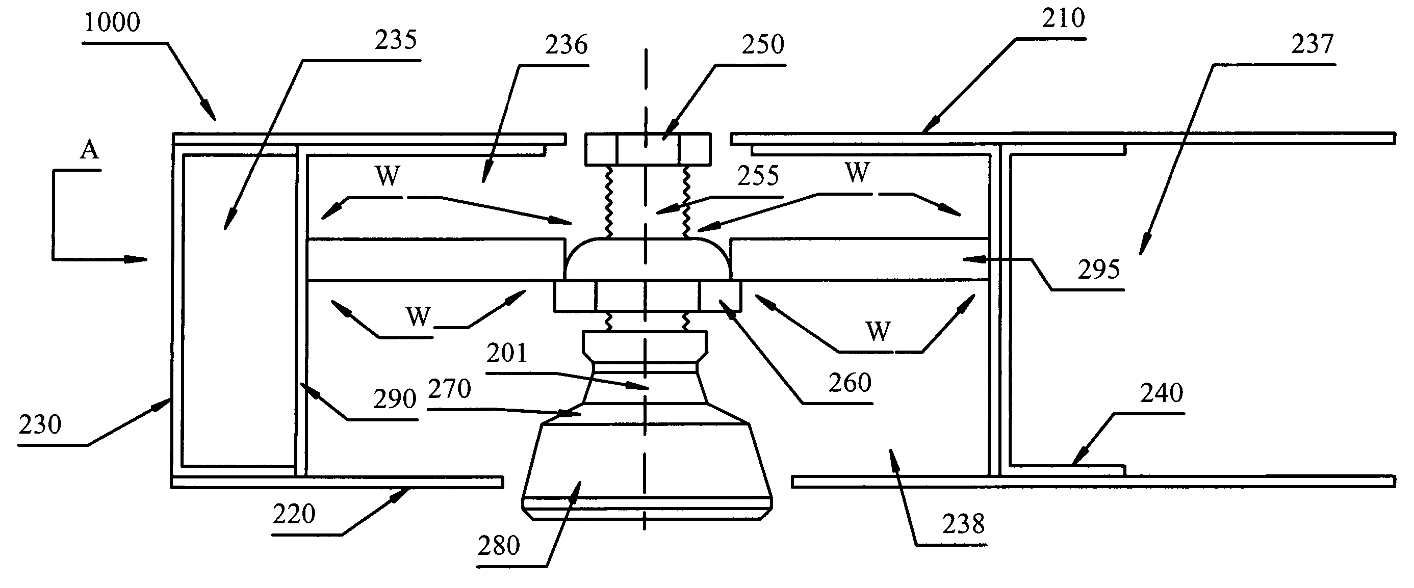
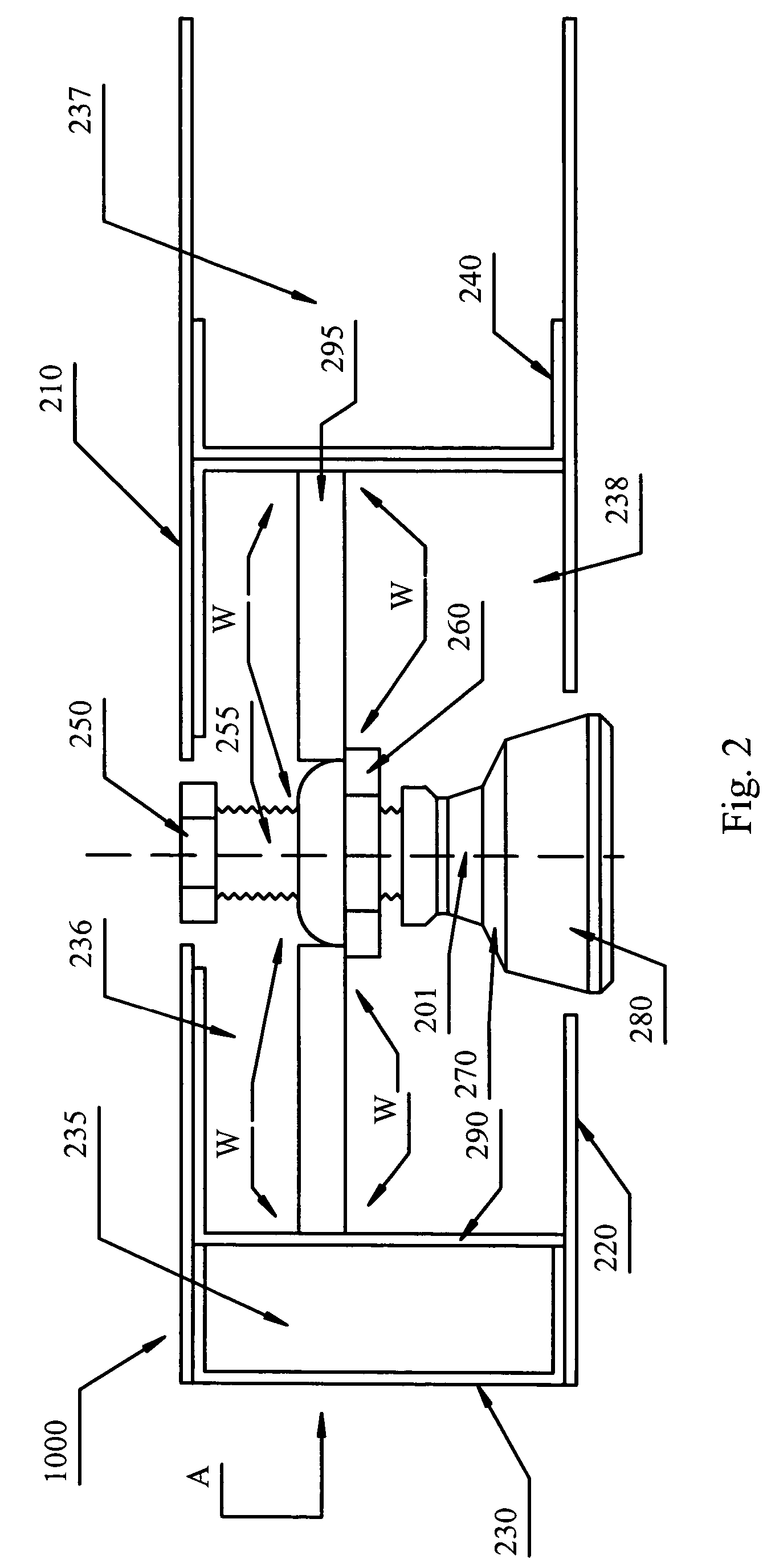
[0018]FIG. 2 illustrates an embodiment of an inventive isolator installed near an end of an acoustic floor according to the method of the present invention. Acoustic floor 1000 comprises an upper steel plate 210 and a lower steel plate 220. A C-channel 230 made of nominally 11-gauge steel is at an end of acoustic floor 1000. Another similar C-channel 240 is placed inward from the end of acoustic floor 1000 a distance sufficient to accommodate the isolator assembly to be herein described.

[0019]The isolator assembly includes a bolt 250 with a threaded section 255 that is threaded through an acorn nut 260 and into a swivel leveling mount 270 which swivels about a point 201. A swivel leveling mount with a 5000 lb load rating may be obtained from McMaster Carr, part number 6103k22. See www.mcmaster.com. A bolt that will fit this part is part number 92240a723. An acorn or dome nut that this bolt will thread through is part number 94301a160.

[0020]Attached to, or integrated into, swivel lev...


PUM


Abstract

An isolator is partially but substantially recessed in an acoustic floor and a leveling mechanism at least partially recessed in the acoustic floor is connected to the acoustic isolator to adjust the height of the acoustic floor when the floor is in place.

Description

TECHNICAL FIELD OF THE INVENTION[0001]The present invention relates to acoustics and methods of sound-proofing rooms, and more particularly to methods of mounting an acoustic structure such as an acoustic enclosure upon a host surface such as a floor of a room enclosing the acoustic structure.BACKGROUND OF THE INVENTION[0002]In the field of acoustics, one often desires to place an acoustic structure upon a host surface such as the floor of a host building enclosing the acoustic structure. For example, an acoustic enclosure such as a sound-proof room is placed on a floor inside a building. Such acoustic enclosures include those described in U.S. Pat. No. 6,581,724 issued to Acoustic Systems, Inc., a division of ETS Lindgren, L. P., the assignee of the present invention.[0003]In many applications one desires to prevent sound waves from being transmitted between the host surface and the acoustic enclosure. For this reason, the acoustic structure is mounted upon the surface using a soun...

Claims


Application Information

Patent Timeline
Patent Type & Authority Patents(United States)
IPC IPC(8): F16F15/02E04G1/22F16F7/00F16M11/32E04B5/00F16M11/24E04F15/024E04F15/20
CPCE04F15/02476E04F15/20
Inventor PHILLIPS, JOHN A.HAYES, ROBERT W.
Owner ETS-LINDGREN
Why Eureka
Try Eureka