Optical device, illumination apparatus, and color illumination apparatus
a technology of illumination apparatus and optical device, which is applied in the direction of mechanical apparatus, lighting and heating apparatus, instruments, etc., can solve the problems of wasteful throwing away of colors other than the separated color, and the method of compacting the entire illumination apparatus substantially,
- Summary
- Abstract
- Description
- Claims
- Application Information
AI Technical Summary
Problems solved by technology
Method used
Image
Examples
first embodiment
[0121][First Embodiment]
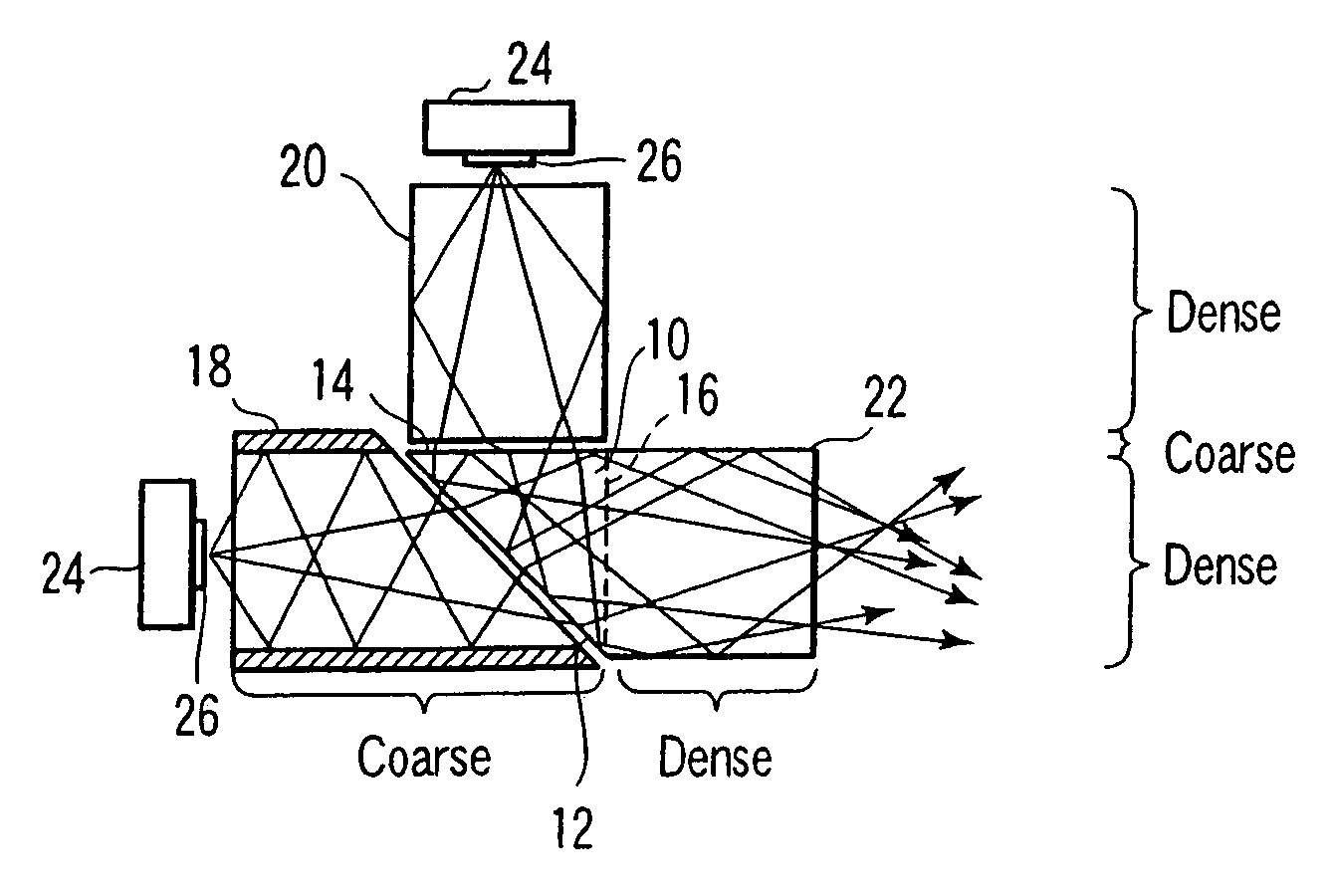
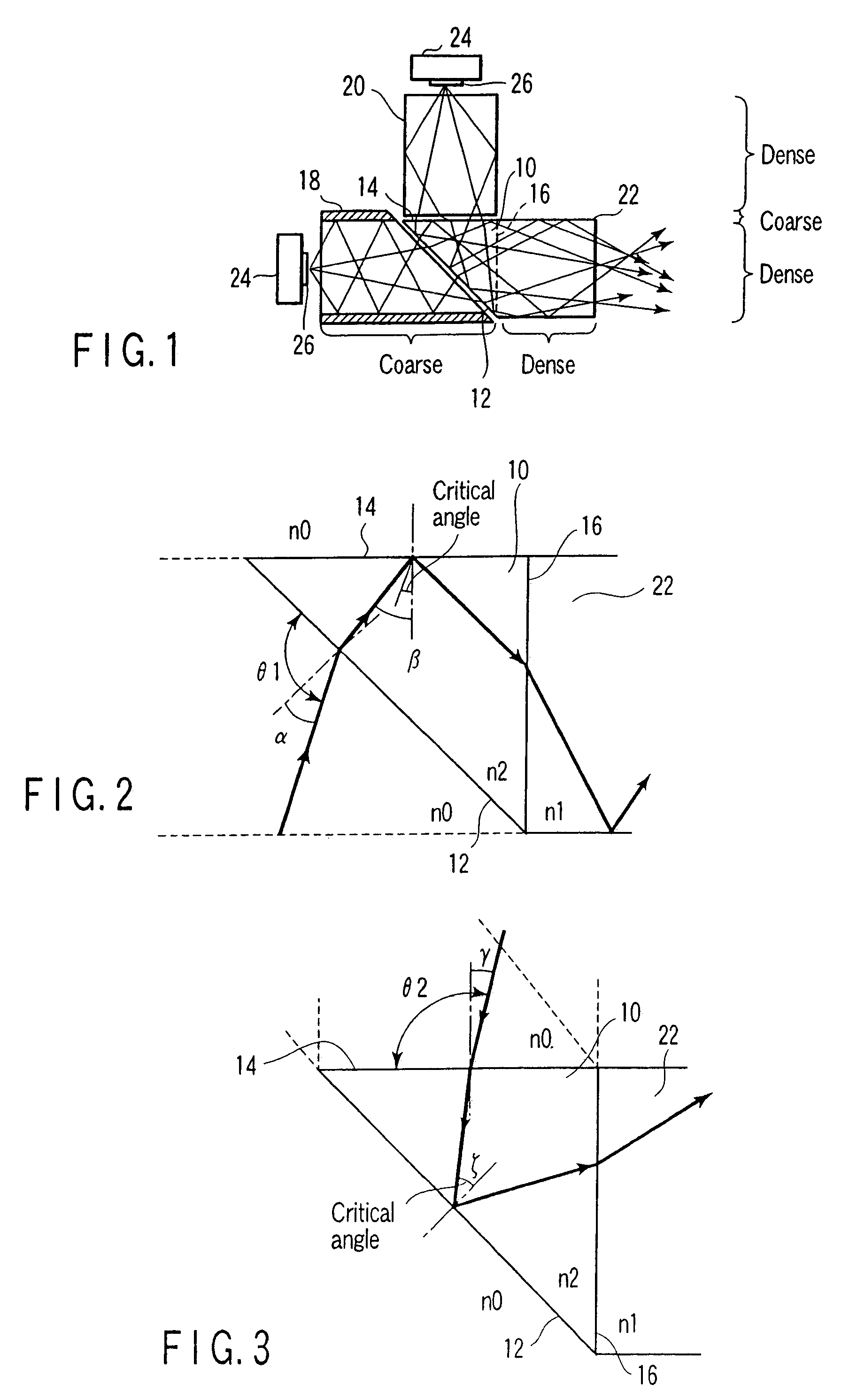
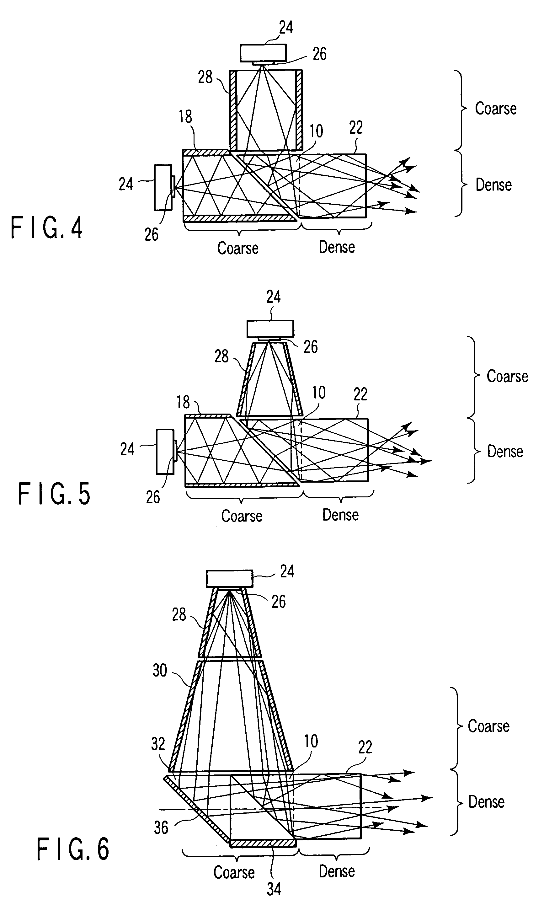
[0122]As shown in FIG. 1, an optical device according to a first embodiment of the present invention includes a prism 10 including: a first incidence plane 12 on which rays coming from a first direction strike; a second incidence plane 14 on which rays coming from a second direction, different from the first direction, strike; and an emission plane 16 for emitting rays incident upon the first and second incidence planes 12, 14 in a predetermined direction which is different from the first and second directions.
[0123]Moreover, the optical device includes: a hollow light pipe 18 including a reflective surface on its inner surface, which is a light guiding member for guiding the rays coming from the first direction onto the first incidence plane 12; and a solid rod 20 which is a light guiding member for guiding the rays coming from the second direction onto the second incidence plane 14. In this case, emission ports of the light pipe 18 and rod 20 are aligned / ar...
second embodiment
[0132][Second Embodiment]
[0133]When the rod 20 is disposed perpendicularly to the second incidence plane 14 of the prism 10 as shown in FIG. 1, some of the rays are not in a range of an incident angle θ2 capable of guiding the light by the total reflection conditions as shown in FIG. 3, and result in a loss of quantity of light. To solve the problem, in the second embodiment, as shown in FIG. 7, an extending direction of the rod 20 is inclined with respect to the second incidence plane 14 of the prism 10. With this configuration, the ray incident upon the second incidence plane 14 of the prism 10 can be brought into the range of θ2, eventually the rays reflected by the first incidence plane 12 can be increased, and bright light is emitted from the emission plane 16.
[0134]Moreover, in the second embodiment, in the same manner as in the first embodiment, needless to say, the light pipe 28 may also be used instead of the rod 20 as shown in FIG. 8, or the rod 20 or the light pipe 28 may...
third embodiment
[0135][Third Embodiment]
[0136]The present embodiment relates to an illumination apparatus using the optical device described in the first and second embodiments.
[0137]As shown in FIGS. 10 and 10A, LED chips 26 are mounted on inner peripheries of substrates (not shown) of three stages formed in an annular form (donut type). Here, some of the LED chips 26 have emission colors of red (R), green (G), blue (B). In the present embodiment, two LED chips (R) 26R, two LED chips (B) 26B, and four LED chips (G) 26G form one set, and two sets are disposed on the inner periphery of the annular light-emitting substrate in each of three stages. In this case, the LED chips 26 having the same emission color are disposed in positions facing each other. The chips are also configured to have the same emission color in the same position of the adjoining stages. In this case, light-emitting surfaces of the LED chips 26 in the same position of the adjoining stages are disposed to have a mutually parallel ...
PUM
 Abstract
Description
Claims
Application Information
 - R&D
- Intellectual Property
- Life Sciences
- Materials
- Tech Scout
- Unparalleled Data Quality
- Higher Quality Content
- 60% Fewer Hallucinations
Browse by: Latest US Patents, China's latest patents, Technical Efficacy Thesaurus, Application Domain, Technology Topic, Popular Technical Reports.
© 2025 PatSnap. All rights reserved.Legal|Privacy policy|Modern Slavery Act Transparency Statement|Sitemap|About US| Contact US: help@patsnap.com


