
Immersed reflective polarizer with angular confinement in selected planes of incidence

a reflective polarizer and angular confinement technology, applied in the field of optical films, can solve the problem that the law of snell's law no longer operates to prevent the propagation of light through the film at supercritical, and achieve the effects of simplifying the manufacturing process, reducing inventory, and enhancing the brightness and contrast ratio of the display

Active Publication Date: 2012-11-01
3M INNOVATIVE PROPERTIES CO
View PDF5 Cites 23 Cited by
  • Summary
  • Abstract
  • Description
  • Claims
  • Application Information

AI Technical Summary

Benefits of technology

The patent describes optical films that can reflect and transmit light in a way that mimics the properties of a reflective polarizer and a mirror, depending on the angle at which the light enters the film. These films can be used in display constructions to enhance the brightness and contrast of the display. The films can be combined with other optical components in a laminated construction, which can simplify the manufacturing process and reduce inventory and cost. The patent also describes a method for using the films as a reflective polarizer in a recycling cavity or system. The films have a unique construction that includes a plurality of microlayers and an optically thick low index layer, which can selectively transmit and reflect light at different angles and polarizations. The low index layer has an ultra low refractive index, which can limit the propagation of highly oblique light and redirect it back towards the microlayers. The patent also discusses the use of these films in display constructions and the methods for manufacturing them.

Problems solved by technology

However, eliminating the air layer that normally contacts the major surfaces of an optical film, and replacing that air layer with other optical media in which the optical film becomes “immersed”, can pose design challenges.
Snell's law no longer operates to prevent the propagation of light through the film at supercritical angles.

Method used


Image

  • Immersed reflective polarizer with angular confinement in selected planes of incidence
  • Immersed reflective polarizer with angular confinement in selected planes of incidence
  • Immersed reflective polarizer with angular confinement in selected planes of incidence

Examples


Embodiment Construction

[0039]Most optical films that are suitable for use in displays, backlights, luminaries, and the like have optical transmission and reflection characteristics that change with the angle of incidence of light. Multilayer optical films, for example, which comprise a plurality of microlayers that are sufficiently thin so that some light is reflected from a plurality of the microlayer interfaces to undergo constructive or destructive interference to provide the desired reflective or transmissive properties, are specifically designed for a particular range of entrance and / or exit angles in a particular medium—typically air. Similarly, surface structured films, such as prismatic brightness enhancement films, are also specifically designed for a particular range of entrance and / or exit angles in air. For given incidence angles in air, propagation angles and exit angles for such optical films are determined by well known formulas such as Snell's law for refraction or other formulas such as t...


PUM


Abstract

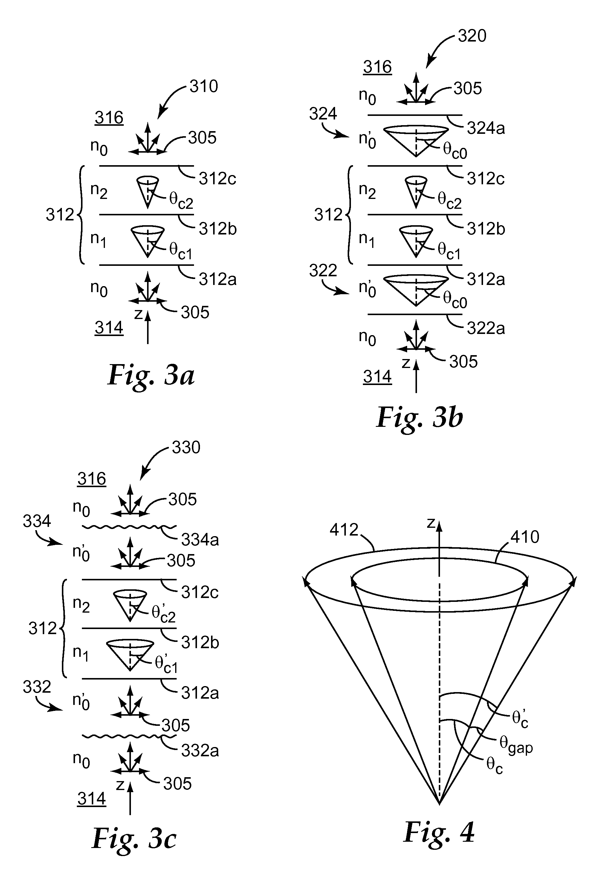
A film construction (330) includes a broad band reflective polarizing film (312) that may be immersed in an ultra low refractive index medium (332, 334). The reflecting polarizing film is characterized by a pass axis and a block axis, and its reflectivity for white light of the pass state polarization increases with increasing incidence angle to provide a compressed or narrowed viewing cone selectively in one plane of incidence. In some embodiments, the plane of incidence associated with the compressed viewing cone is aligned with the pass axis. In other embodiments it is aligned with the block axis.

Description

FIELD OF THE INVENTION[0001]This invention relates generally to optical films whose reflection and transmission characteristics are determined in large part by constructive and destructive interference of light reflected from interfaces between microlayers within the film, with particular application to combinations of such films with other components, such as components suitable for use in display systems. The invention also relates to associated articles, systems, and methods.BACKGROUND[0002]Reflective polarizers composed of a plurality of microlayers whose in-plane refractive indices are selected to provide a substantial refractive index mismatch between adjacent microlayers along an in-plane block axis and a substantial refractive index match between adjacent microlayers along an in-plane pass axis, with a sufficient number of layers to ensure high reflectivity for normally incident light polarized along the block axis while maintaining low reflectivity and high transmission for...

Claims


Application Information

Patent Timeline
Patent Type & Authority Applications(United States)
IPC IPC(8): G02B5/30
CPCG02F1/13362G02B5/305G02B5/3041
Inventor WEBER, MICHAEL F.LIU, TAONEVITT, TIMOTHY J.
Owner 3M INNOVATIVE PROPERTIES CO
Learn More