
Immersed reflective polarizer with high off-axis reflectivity

a reflective polarizer and high reflectivity technology, applied in the field of optical films, can solve the problem that the law of snell's law no longer operates to prevent the propagation of light through the film at supercritical, and achieve the effects of simplifying the manufacturing process, reducing inventory, and enhancing the brightness and contrast ratio of the display

Active Publication Date: 2012-08-16
3M INNOVATIVE PROPERTIES CO
View PDF5 Cites 19 Cited by
  • Summary
  • Abstract
  • Description
  • Claims
  • Application Information

AI Technical Summary

Benefits of technology

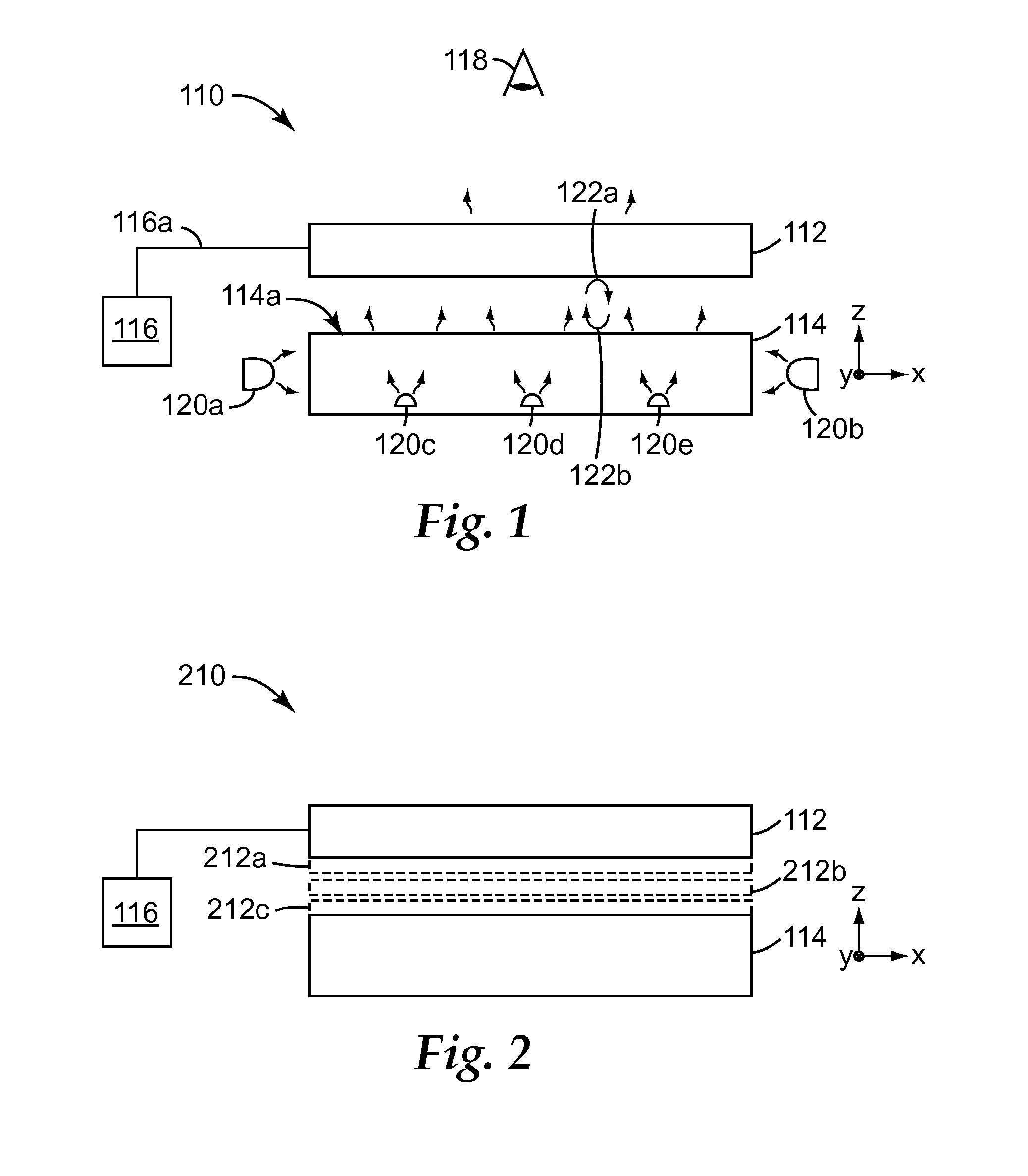
[0005]Such an optical film and laminated construction may, if desired, be used in a display to selectively transmit broadband light traveling in an axial or near-axial direction and having a pass state polarization, while substantially reflecting broadband light of the pass state traveling at highly oblique angles, and reflecting broadband light having a block state polarization traveling at any angle, over a large area. Confining transmitted light of the pass state to a relatively narrow or compressed cone of propagation angles corresponding to axial or near-axial directions can advantageously be used to enhance axial brightness and contrast ratio of the display, particularly when the film or laminate is used in a recycling cavity or system such that at least some of the reflected light, whether of the pass state or block state, can be reflected by another component and converted to axial or near-axial light of the pass state.
[0006]Combining one or more optical film with other display components in a laminated construction can be advantageous for display manufacturers and suppliers in a number of ways, e.g., accelerating and simplifying the manufacturing process, reducing inventory, and reducing cost. However, eliminating the air layer that normally contacts the major surfaces of an optical film, and replacing that air layer with other optical media in which the optical film becomes “immersed”, can pose design challenges. Snell's law no longer operates to prevent the propagation of light through the film at supercritical angles. An ultra low index (ULI) coating or other optically thick layer can approximate an air gap, but such a layer still effectively allows light to propagate a range of supercritical angles
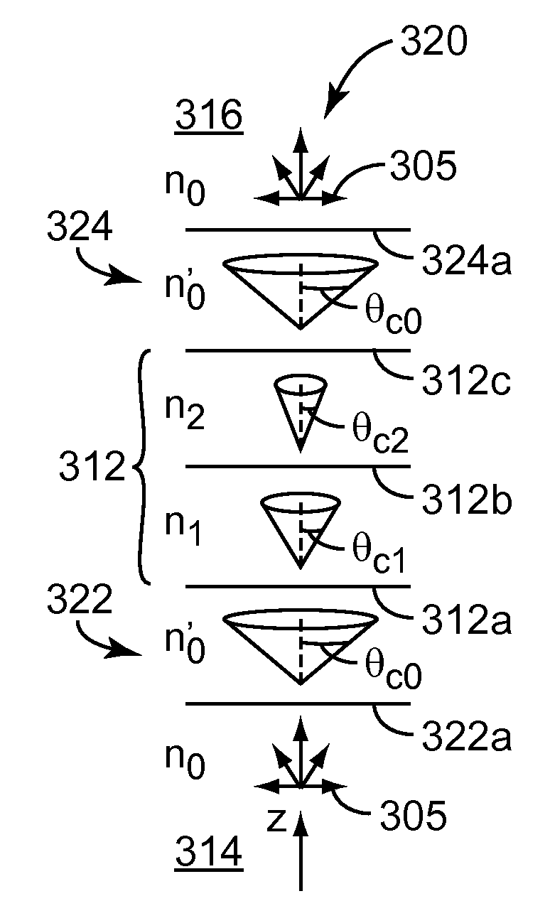
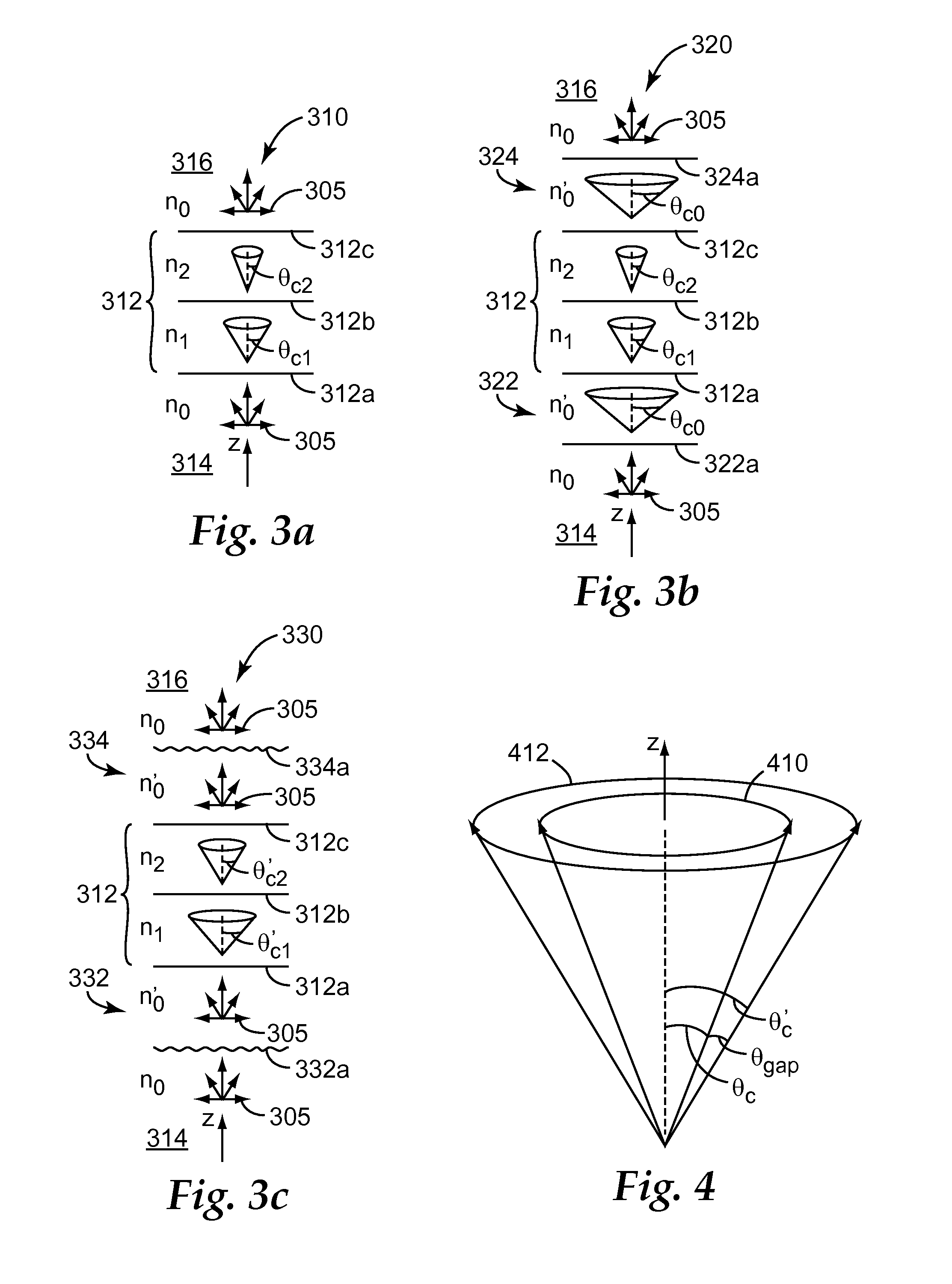
[0007]The present application therefore discloses, inter alia, a film construction that includes a plurality of microlayers and an optically thick low index layer. The plurality of microlayers can be configured to selectively transmit and reflect light as a function of angle and polarization over an extended wavelength region including visible wavelengths, the microlayers defining a pass axis for normally incident visible light of a first polarization and a block axis for normally incident visible light of a second polarization. The microlayers are also preferably characterized by increased reflectivity at oblique angles so as to transmit visible light of the first polarization in a compressed viewing cone. The optically thick low index layer preferably has an ultra low refractive index, e.g., from 1.1 to 1.3, or from 1.15 to 1.25, and is coupled to the microlayers in such a way as to limit propagation of highly oblique light in the microlayers (e.g. in cases where the low index layer is disposed between the microlayers and the source of highly oblique light), or to redirect such highly oblique propagating light back towards the microlayers (e.g. in cases where the microlayers are disposed between the low index layer and the source of highly oblique light).

Problems solved by technology

However, eliminating the air layer that normally contacts the major surfaces of an optical film, and replacing that air layer with other optical media in which the optical film becomes “immersed”, can pose design challenges.
Snell's law no longer operates to prevent the propagation of light through the film at supercritical angles.

Method used


Image

  • Immersed reflective polarizer with high off-axis reflectivity
  • Immersed reflective polarizer with high off-axis reflectivity
  • Immersed reflective polarizer with high off-axis reflectivity

Examples


example nu-1

Immersed Film with No Ultra Low Index Layer

[0191]If the index set of the reflective polarizer is (nx=1.80, ny=1.67, nz=1.505) for the “high” index layers and n=1.585 for the “low” index layers, the right band edge for p-pol light does not drop below about 600 nm if the film is immersed in an index of 1.49. These film indices can be obtained with an asymmetrical biaxial orientation and heat setting of a PEN or a coPEN film having a very high PEN content, e.g. 95% PEN or greater. A ratio of orientation for the block axis to the pass axis direction can be about 2:1, although one can easily vary this ratio to optimize the nx vs. ny index. The low index material can be made using a blend of, e.g., PETg and a coPEN. All s-polarized visible light is reflected and p-polarized light below 650 nm is reflected at angles up to about 77 degrees.

[0192]Using the suggested indices and materials listed above for this example, a continuously graded stack of 550 alternating layers of the low and high ...

example nu-2

PETg / coPEN 90-10 Ultra Wide Band Polarizer

[0194]In order to demonstrate that an optical film can be made with the ultra wide bandwidths described in Example NU-1, and with an acceptable level of uniformity of transmission vs. wavelength over such a wide band, the following two films were made and then laminated with an optical adhesive. The first film reflects from about 400 nm to 900 nm and the second film reflects from about 800 nm to 1800 nm. The bandedges were designed to be gradual in order that the transitional overlap in the spectra from one film to the other in the laminate is relatively smooth. Both films were made using a feedblock method such as that described in U.S. Pat. No. 6,783,349 (Neavin et al.) with 275 alternating layers of a 90 / 10 coPEN (90% PEN / 10% PET) and PETg (available from Eastman Chemicals, Tennessee). The first film was optimized for uniformity of transmission and bandage slopes, with bandages of about 400 and 900 nm. The extrusion casting wheel was then...


PUM


Abstract

A film construction (320) includes a broad band reflective polarizing film (312) that may be immersed in an ultra low refractive index medium (322, 324). The reflecting polarizing film is characterized by a pass axis and a block axis, and its reflectivity for white light of the pass state polarization increases with increasing incidence angle to provide a compressed or narrowed viewing cone in one or two planes.

Description

FIELD OF THE INVENTION[0001]This invention relates generally to optical films whose reflection and transmission characteristics are determined in large part by constructive and destructive interference of light reflected from interfaces between microlayers within the film, with particular application to combinations of such films with other components, such as components suitable for use in display systems. The invention also relates to associated articles, systems, and methods.BACKGROUND[0002]Reflective polarizers composed of a plurality of microlayers whose in-plane refractive indices are selected to provide a substantial refractive index mismatch between adjacent microlayers along an in-plane block axis and a substantial refractive index match between adjacent microlayers along an in-plane pass axis, with a sufficient number of layers to ensure high reflectivity for normally incident light polarized along the block axis while maintaining low reflectivity and high transmission for...

Claims


Application Information

Patent Timeline
Patent Type & Authority Applications(United States)
IPC IPC(8): G02B5/30
CPCG02F1/13362G02B5/305
Inventor WEBER, MICHAEL F.
Owner 3M INNOVATIVE PROPERTIES CO
Learn More