Differential planetary gear apparatus

a technology of planetary gear and gear shaft, which is applied in the direction of differential gearings, mechanical equipment, gearings, etc., can solve the problems of unsuitability for high-speed rotation, large radial size of differential gear apparatus, and complicated structure of such gearing apparatus, and achieve accurate and smooth speed change, high mechanical efficiency, and high efficiency

Inactive Publication Date: 2007-05-01
EBARA CORP
View PDF18 Cites 12 Cited by
  • Summary
  • Abstract
  • Description
  • Claims
  • Application Information

AI Technical Summary

Benefits of technology

[0014]The present invention has been made in view of the above drawbacks. It is therefore an object of the present invention to provide a differential planetary gear apparatus which eliminates a mechanical unbalance and has a high mechanical efficiency, and can cope with a high-speed operation. It is another object of the present invention to provide a starting apparatus and method for a differential planetary gear apparatus which can reduce a load on a drive source (e.g., a large-capacity constant-speed motor) during the starting.

Problems solved by technology

However, this double-pinion-type differential planetary gear apparatus has a number of components, and hence the structure thereof becomes complicated and the radial size thereof becomes large.
Further, because of mechanical unbalance in the radial direction, this type of differential planetary gear apparatus is unsuitable for a high-speed rotation.
Furthermore, since a rotational speed is controlled by the brake devices B1 and B3, its control accuracy is low.
Providing such another starting drive means causes an increase in installation cost and other cost, and also causes a complicated structure.
Otherwise, it is difficult to increase the rotational speed of the above-mentioned drive source to nearly the rated rotational speed.

Method used


Image

  • Differential planetary gear apparatus
  • Differential planetary gear apparatus
  • Differential planetary gear apparatus

Examples


first embodiment

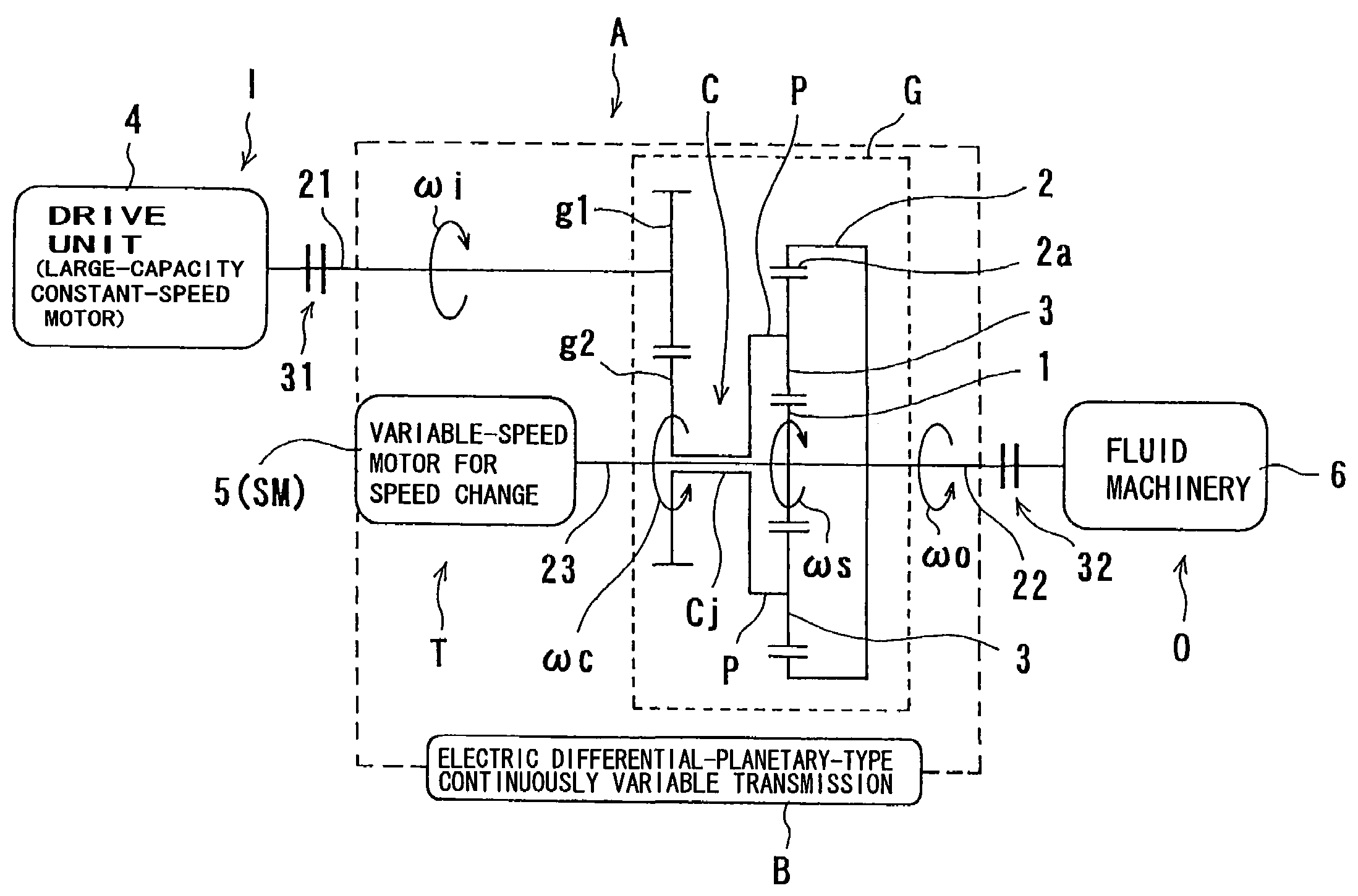
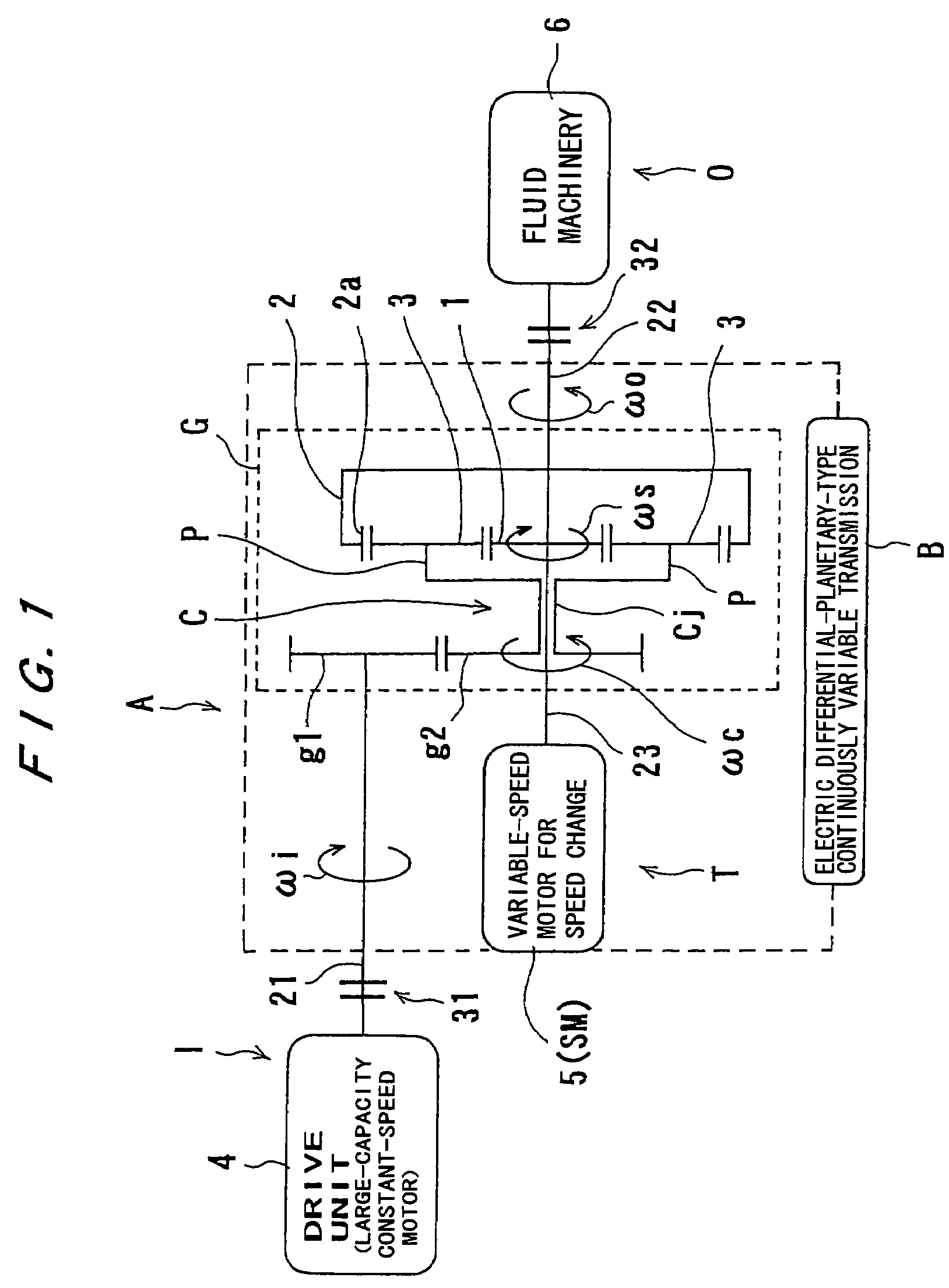
[0054]First, a differential planetary gear apparatus will be described with reference to FIG. 1.

[0055]In FIG. 1, the differential planetary gear apparatus, which is indicated by a reference sign A as a whole, comprises an electric differential-planetary-type continuously variable transmission B having an input shaft 21 and an output shaft 22, a drive unit 4 comprising a large-capacity constant-speed motor disposed at an input side I, i.e., connected to one end of the input shaft 21 via an input-side clutch 31, and a fluid machinery 6, such as a turbo machinery, disposed at an output side O, i.e., connected to one end of the output shaft 22 via an output-side clutch 32.

[0056]The electric differential-planetary-type continuously variable transmission B comprises a differential planetary gear assembly G having an input shaft and an output shaft (i.e., the input shaft 21 and the output shaft 22) and a speed-change drive shaft 23, and a small-capacity variable-speed motor 5 for speed ch...

second embodiment

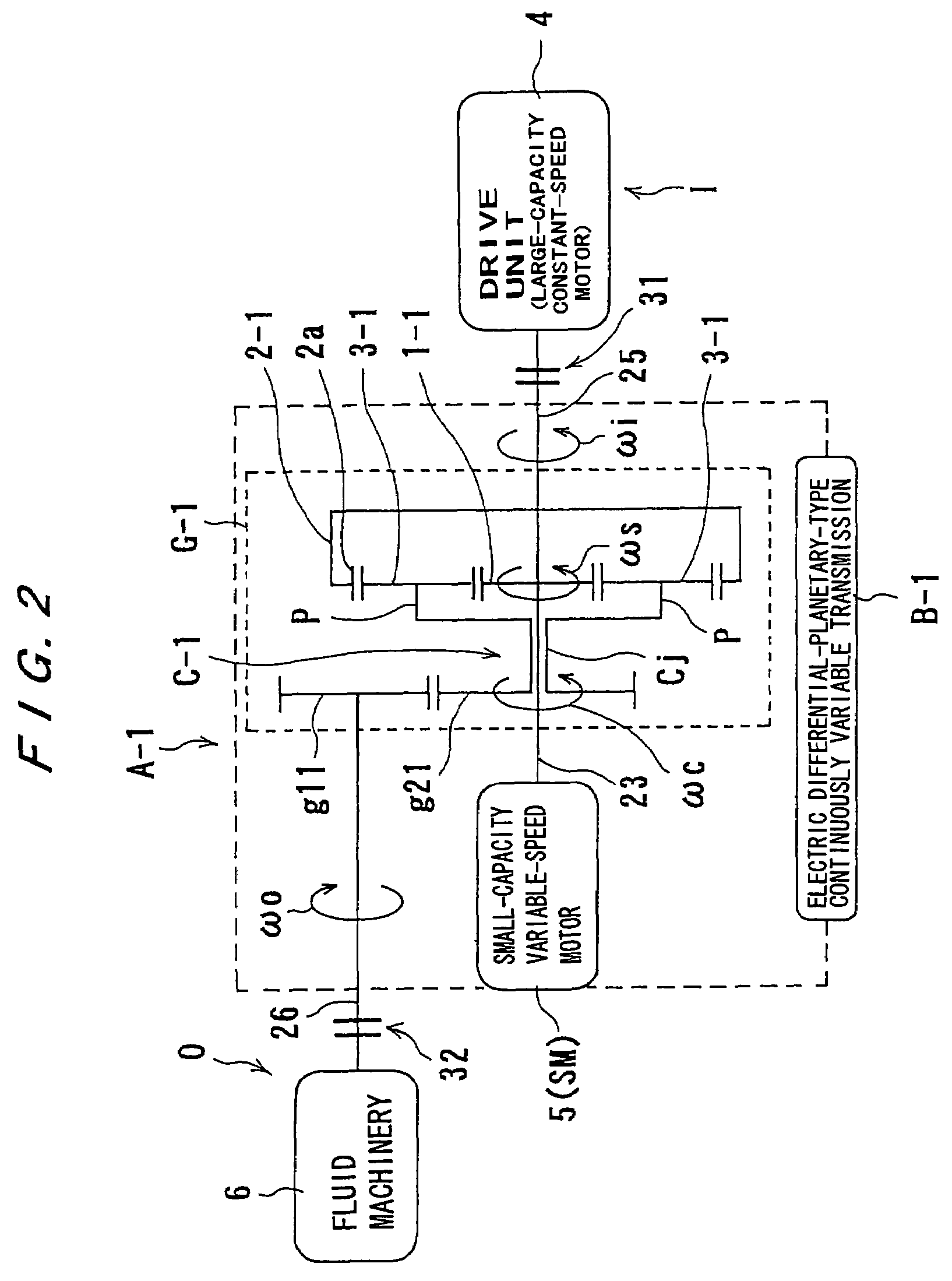
[0076]Next, a second embodiment will be described with reference to FIG. 2.

[0077]In FIG. 2, a differential planetary gear apparatus, which is indicated by a reference sign A-1 as a whole, comprises an electric differential-planetary-type-type continuously variable transmission B-1 having an input shaft 25 (disposed at the right side in the drawing) and an output shaft 26 (disposed at the left side in the drawing), a drive unit 4 comprising a large-capacity constant-speed motor disposed at an input side I, i.e., connected to one end of the input shaft 25 via an input-side clutch 31, and a fluid machinery 6 disposed at an output side O, i.e., connected to one end of the output shaft 26 via an output-side clutch 32.

[0078]The electric differential-planetary-type-type continuously variable transmission B-1 comprises a differential planetary gear assembly G-1 having an input shaft and an output shaft (i.e., the input shaft 25 and the output shaft 26) and a speed-change drive shaft 23, and...

third embodiment

[0086]Next, a third embodiment will be described with reference to FIG. 3.

[0087]In FIG. 3, a differential planetary gear apparatus, which is indicated by a reference sign A-2 as a whole, has a structure in which a speed-change gear 7, such as a speed-increasing gear or a speed-decreasing gear, is added to the first embodiment shown in FIG. 1. This speed-change gear 7 is disposed on the output shaft 22 at a location between the ring gear 2 and the output-side clutch 32.

[0088]According to the third embodiment shown in FIG. 3, the speed change can be performed in a wider speed range, compared with the first embodiment shown in FIG. 1.


PUM


Abstract

A differential planetary gear apparatus has a single-pinion-type structure in which one planetary gear (3) is arranged in a radial direction and one or more planetary gears (3) are arranged in a circumferential direction in a region between a sun gear (1) and a ring gear (2), a drive source (4), a speed-change motive source (5), and a driven unit (6) are disposed at any one of an input side (I), an output side (O), and a speed-change side (T). The speed-change motive source (5) includes an electric motor.

Description

TECHNICAL FIELD[0001]The present invention relates to a differential planetary gear apparatus, and a starting apparatus and method for a differential planetary gear apparatus.BACKGROUND ART[0002]In a differential planetary gear apparatus, there has recently been a demand for using a motor, e.g., an inverter motor, as a rotational drive source for speed change in order to accurately control a transmission ratio.[0003]As one of apparatuses which can meet such a demand, there has been known a differential planetary gear apparatus shown in FIG. 14, for example.[0004]The differential planetary gear apparatus shown in FIG. 14 comprises a sun gear Sg fixed to a tip end of an input shaft 55 connected to a drive source 50, a plurality of first planetary gears (pinion gears) P1 disposed radially outwardly of the sun gear Sg and meshing with this sun gear Sg, a plurality of second planetary gears (pinion gears) P2 meshing with the first planetary gears P1, a ring gear Rg having internal teeth ...

Claims


Application Information

Patent Timeline
Patent Type & Authority Patents(United States)
IPC IPC(8): F16H48/06F16H3/72F16H48/10
CPCF16H3/724F16H3/725
Inventor KIMURA, KATSUMIMIWA, TOSHIOTAKASHIMA, MICHIOUSAMI, TAKESHISUGIYAMA, KAZUHIKO
Owner EBARA CORP
Why Eureka
Try Eureka