Force Sending Device and A Flight Control Device Comprising Such A Force Sensing Device

a technology of force sensing and sending device, which is applied in the direction of force/torque/work measurement apparatus, gearing, instruments, etc., can solve the problems of not being able to meet all of the aforementioned requirements and singular demands of the range relative to the flight control device, and achieves reasonable cost, high mechanical efficiency, and the effect of low play and friction

Active Publication Date: 2018-09-06
FLY BY WIRE SYST FRANCE
View PDF0 Cites 0 Cited by
  • Summary
  • Abstract
  • Description
  • Claims
  • Application Information

AI Technical Summary

Benefits of technology

[0011]The invention therefore aims to resolve the drawbacks of the prior art by proposing a force sensing device for a flight control device of an aircraft for which both the play and friction are particularly low, or even nonexistent, and a high mechanical efficiency, at a reasonable cost.
[0019]One idea at the base of the invention is to provide a transmission of the movement between the action member and the rotary device through rolling contacts, owing to the implementation of the mechanical reducing gear with a screw-nut system with rolling elements. By providing a transmission, preferably exclusively, by rolling contacts, the mechanical reducing gear thus has a particularly low, or even nonexistent, play and friction, and a high mechanical efficiency, relative to a traditional reducing gear with gear train. In the invention, one thus converts the rotating movement of the action member relative to the support into a translational movement of the nut relative to the stator along the secondary axis, then this translational movement into a rotational movement of the screw and the rotor relative to the stator, around the secondary axis. The implementation of a screw-nut system, rather than a gear train, further makes the force sensing device less sensitive to temperature variations. The implementation of such a screw-nut system makes it possible to obtain the aforementioned effects and advantages while having a reasonable cost, inasmuch as such a screw-nut system is inherently relatively inexpensive compared to other systems with rolling elements that are more elaborate and less standard.
[0023]the connecting rod is attached to the nut using a second pivot link that connects the connecting rod to the nut, such that the connecting rod rotates freely relative to the nut around a second connecting rod axis parallel to the primary axis and orthogonal to the secondary axis.
[0032]that is attached to the connecting rod by the second pivot link, such that the first arm rotates freely relative to the connecting rod around the axis of the second pivot link, and

Problems solved by technology

(degrees Celsius) and 60° C. Indeed, the range relative to flight control devices is singularly demanding, not only due to the relative constraints of the aeronautics field, but also because it is necessary to ensure perfect control ergonomics for the pilot, who acts with great precision and sensitivity on the flight controls.
In the known devices, the mechanical reducing gear is generally made up of a gear train, which generally does not make it possible to meet all of the aforementioned requirements, some of which are antagonistic, namely the absence of friction and the absence of play.

Method used


Image

  • Force Sending Device and A Flight Control Device Comprising Such A Force Sensing Device
  • Force Sending Device and A Flight Control Device Comprising Such A Force Sensing Device
  • Force Sending Device and A Flight Control Device Comprising Such A Force Sensing Device

Examples


first embodiment

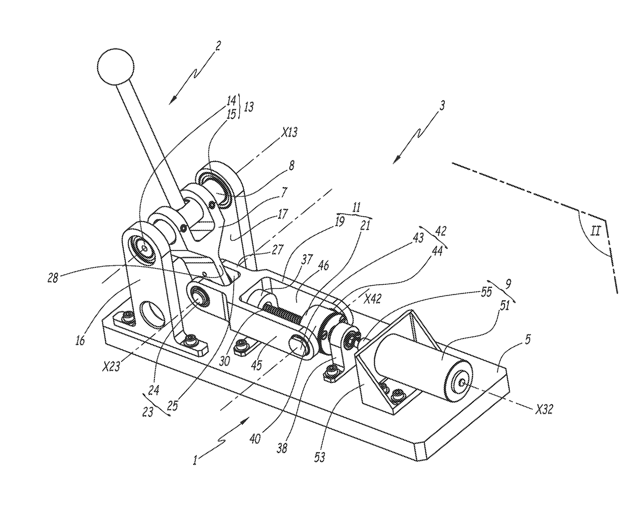
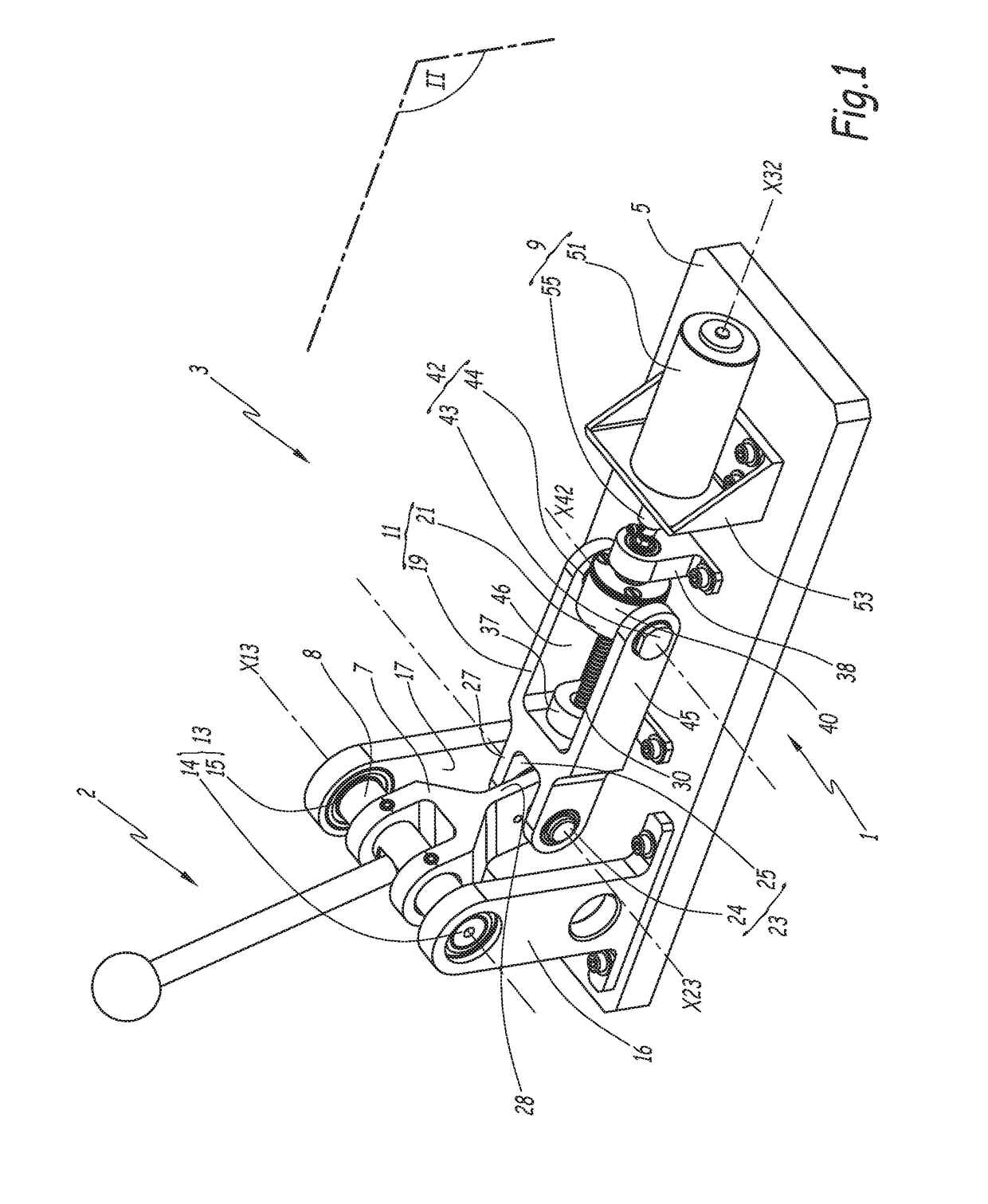
[0051]FIG. 1 shows a flight control device 3. This flight control device 3 is configured to equip an aircraft, which is not illustrated. For example, the aircraft is an airplane or a helicopter. The flight control device 3 is in particular designed to be integrated into a cockpit of this aircraft, as part of a man-machine interface for piloting the aircraft.

[0052]The flight control device 3 comprises a force sensing device 1 and a control member 2. In the case at hand, the member 2 forms a control lever able to be actuated by hand, preferably by a pilot of the aircraft, or by a crew member of the aircraft. Preferably, the flight control device 3 forms the reducing chain of an aircraft mini stick. Alternatively, the control member 2 can be actuated by foot, for example forming a control pedal. The flight control device 3 acts on one or several control surfaces of the aircraft, such as foil flaps or ailerons, or on the orientation of a propeller.

[0053]The force sensing device 1 compri...

third embodiment

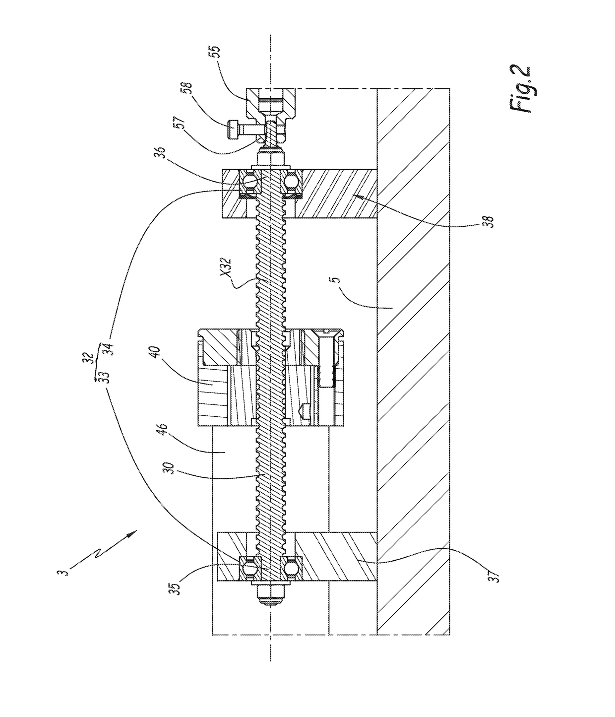
[0112]In this third embodiment, the stator 251 is attached to the support of the device 201 while rotating freely, around a stator axis X251, relative to said support. To that end, a pivot link, not illustrated, is preferably provided, connecting the stator 251 to the support. The pivot link for example comprises one or several bearings with rolling elements. The stator 251 is therefore not stationary relative to the support, and may on the contrary pivot freely around the axis X251. In this configuration, the stator 251 is nevertheless connected in rotation to the support around a secondary axis X232. The axis X251 is parallel to the axis X213.

[0113]Depending on the application, it is provided that the device 209 is active, passive, or semi-active, according to the previous definitions.

[0114]The device 201 comprises a mechanical reducing gear 211, which, with a reduction ratio, links the rotation of the action member 207 relative to the support around the axis X213, with the rotati...

fourth embodiment

[0131]In FIG. 6, the device 301, which is also similar in all points to the device 201 of the embodiment of FIG. 5, further comprises a rotary device 309, in addition to the rotary device 209 already provided for the embodiment of FIG. 5. The rotary device 309 comprises a stator 351 and a rotor 355, hidden by the stator 351 in FIG. 6. The rotor 355 is attached to the stator 351 while rotating freely relative to the stator 351 around the axis X232. The rotor 355 is also connected in rotation with the screw 230 around the axis X232, via the end 235; i.e., opposite the rotor 255 relative to the screw 230. The stator 351 is fastened to the branch 283 of the framework 280; i.e., opposite the stator 251 relative to the framework 280. The device 309 also comprises a means for applying a force sensing torque for the rotation of the rotor 355 relative to the stator 251 around the axis X232. Thus, the device 309 is complementary to the device 209, in that they both apply a force sensing torqu...


PUM

PropertyMeasurementUnit
temperatureaaaaaaaaaa
electrical energyaaaaaaaaaa
torqueaaaaaaaaaa

Abstract

A flight control device of an aircraft including a support, an action member attached to the support rotating freely around a primary axis, a rotary device including a stator, rotatably connected to the support around a secondary axis, and a rotor rotating freely relative to the stator around the secondary axis, the rotary device applying a force sensing torque on the rotor relative to the stator around the secondary axis, and a mechanical reducing gear, which connects, with a reduction ratio, rotation of the action member with rotation of the rotor, the mechanical reducing gear including a screw-nut system with rolling elements, including a screw, attached to the rotor, connected in rotation to the rotor around the secondary axis, and a nut fixed in rotation around the secondary axis relative to the stator and helically connected with the screw around and along the secondary axis via the rolling elements.

Description

CROSS REFERENCE TO RELATED APPLICATIONS[0001]This application claims priority under 35 USC § 119 of French Patent Application No. 17 51803 filed on Mar. 6, 2017.FIELD OF THE INVENTION[0002]The present invention relates to a force sensing device and a flight control device comprising such a force sensing device.[0003]The present invention more particularly relates to the field of aircraft flight control devices. More specifically, the invention relates to the manual controls situated in the man-machine interface of an aircraft. These controls can for example be actuated using a hand or a foot.BACKGROUND OF THE INVENTION[0004]It is known to equip a flight control device with a force sensing device, the latter being designed to apply forces on the flight control device, so as to produce a sensation for the pilot.[0005]A first known type of force sensing device, which can be described as “force-feedback device”, is designed to apply, on the flight control device, forces connected to act...

Claims


Application Information

Patent Timeline
Patent Type & Authority Applications(United States)
IPC IPC(8): B64C13/04F16H25/22F16H21/44G01L5/22
CPCB64C13/04F16H25/2204F16H21/44G01L5/223F16H2025/204F16H2025/2028B64C13/10
Inventor ROUSSEY, BASTIEN
Owner FLY BY WIRE SYST FRANCE
Why Eureka
Try Eureka