System for monitoring conduit obstruction

a monitoring system and conduit technology, applied in the field of physiological parameters monitoring devices, can solve the problems of requiring special equipment, requiring progressive morbidity and mortality, and affecting the quality of life of the patient,

Active Publication Date: 2007-05-01
UIM PRESSURE IMPLANT INC
View PDF14 Cites 158 Cited by
  • Summary
  • Abstract
  • Description
  • Claims
  • Application Information

AI Technical Summary

Benefits of technology

[0010]The invention comprises a telemetric sensing system for noninvasively monitoring pressure and / or pressure gradients in a cardiac conduit. The system includes one or more implantable sensor unit(s) and a companion reader unit. The sensor unit, which is preferably batteryless and wireless is chronically located within the conduit, or around in a close proximity. For valveless conduits, a sensor unit is placed at either end of the conduit, or around it. For valved conduits, one or more sensor units are located both proximal and distal to the valve, allowing the pressure gradient across the valve to be monitored. One sensor unit can indicate occlusion; however, two sensor units will allow the occlusion to be located (e.g. proximal / middle / distal along the conduit). As well, with two sensor units, flow rates may be deduced or estimated. Furthermore, trend analysis of the pressures and / or flow rate within the conduit can allow a time-to-failure estimate.

Problems solved by technology

In any case, the conduits may eventually become calcified and / or stenotic.
Catheterization gives the best assessment, since it can directly measure the pressure gradient across the conduit; however, it carries progressive morbidity and mortality.
Furthermore, all three methods require specialized equipment and they provide only a snapshot of the physiologic status.

Method used


Image

  • System for monitoring conduit obstruction
  • System for monitoring conduit obstruction
  • System for monitoring conduit obstruction

Examples


Embodiment Construction

[0015]The following description of preferred embodiments and methods provides examples of the present invention. The embodiments discussed herein are merely exemplary in nature, and are not intended to limit the scope of the invention in any manner. Rather, the description of these preferred embodiments and methods serves to enable a person of ordinary skill in the relevant art to make, use and perform the present invention.

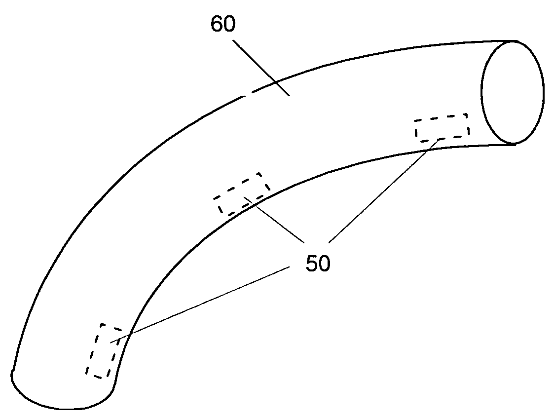
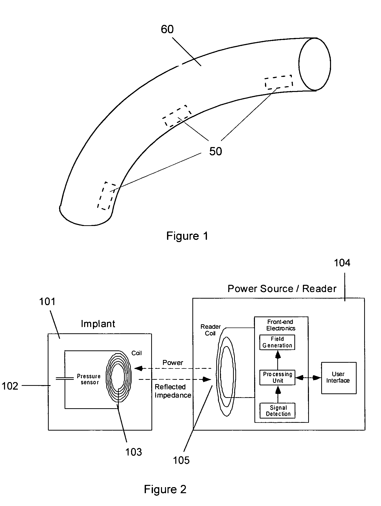
[0016]In order to provide for the effective monitoring, management, and tailoring of treatment for patients with heart defects, the present invention provides a cardiac conduit with a wireless sensing system. The system comprises an external readout unit as well as at least one implantable sensor 50 which is securely anchored in a conduit 60, as shown in FIG. 1 or in the vicinity of the conduit. The readout unit both transmits power to and receives transmitted data from the sensor 50. Data transmitted from the sensor 50 may include pressure, calibration data, ide...


PUM


Abstract

A system for non-invasively monitoring one or more physiological parameters such as pressure and/or pressure gradients in a cardiac conduit adapted for blood bypass flow. The system includes the conduit, at least one sensing device chronically located within the conduit, and a non-implantable readout device. The sensing device includes at least one inductor coil and at least one sensor for monitoring the one or more physiological parameters for diagnosis of the condition of the conduit after the conduit is implanted in a patient. The readout device includes at least one inductor coil allowing electromagnetic telecommunication and electromagnetic wireless powering of the sensing device through the inductor coil thereof.

Description

REFERENCE TO PREVIOUS APPLICATIONS[0001]This application claims the benefit of U.S. Provisional Applications No. 60 / 416,406 filed on Oct. 7, 2002, 60 / 416,407 filed on Oct. 7, 2002, 60 / 416,408 filed on Oct. 7, 2002, and 60 / 416,409 filed on Oct. 7, 2002.FIELD OF THE INVENTION[0002]The present invention relates generally to field of implantable medical devices for monitoring physiological parameters. More particularly, the invention relates to a system utilizing a telemetric implantable physiologic sensor for diagnosing and / or monitoring the conduit obstruction and / or insufficiency in patients that have undergone cardiac conduit surgery.BACKGROUND OF THE INVENTION[0003]Certain heart defects require implantation of a conduit for blood flow to bypass valve aplasia or severe stenosis. These include but not limited to cases of a pulmonary artery only with no aorta. The added conduit may or may not include a valve. There are several types of conduits, including but not limited to:[0004]Homo...

Claims


Application Information

Patent Timeline
Patent Type & Authority Patents(United States)
IPC IPC(8): A61B5/02A61B5/04A61N1/00
CPCA61B5/0031A61B5/0215A61B5/01A61B5/02055A61B5/026A61B5/145A61B5/14532A61B2560/0242A61B2562/028A61B2562/08A61B2562/085
Inventor NAJAFI, NADERRICH, COLLIN ANDERSONMASSOUD-ANSARI, SONBOL
Owner UIM PRESSURE IMPLANT INC
Why Eureka
Try Eureka