
Line interface with analog echo cancellation

a line interface and analog echo technology, applied in the field of communication systems, can solve the problems of significant space saving on the printed circuit board, limit the dynamic range, etc., and achieve the effects of reducing cost, avoiding overlapping, and reducing common-mode nois

Active Publication Date: 2007-05-01
ANALOG DEVICES INC
View PDF22 Cites 5 Cited by
  • Summary
  • Abstract
  • Description
  • Claims
  • Application Information

AI Technical Summary

Benefits of technology

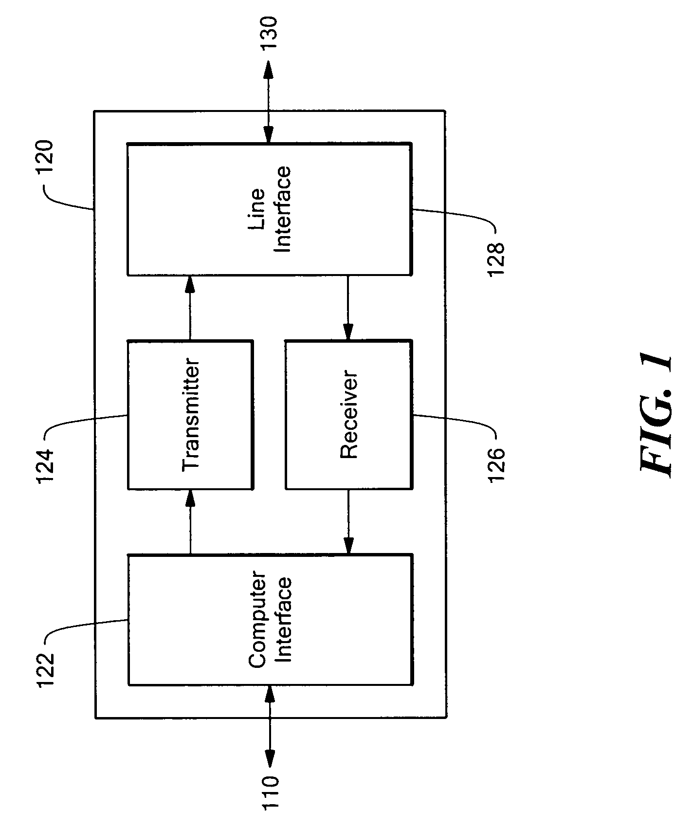
[0014]Disclosed herein are various line interface architectures with analog echo cancellation for a communication device such as a digital subscriber line (DSL) modem. These line interface architectures accomplish echo cancellation without the use of a hybrid filter network, and so the line interface can generally be implemented with fewer external components such as costly, bulky capacitors that are normally used in other line interface architectures to achieve similar performance. Echo cancellation is performed before the signal is input to the receive amplifier, so these architectures generally save two input pins to the receive amplifier. The line interface is preferably balanced, and so the common-mode noise is greatly attenuated. Thus, line interface embodiments of the present invention typically cost less, consume less power, and take up less printed circuit board (PCB) area than other line interface architectures without sacrificing performance in terms of transmit gain, receive gain, hybrid rejection, line termination, and noise.
[0015]In accordance with embodiments of the present invention, the line interface includes a transmit path and a receive path coupled to a communication medium (line) such as a telephone line. The transmit path includes a line driver, a single matching network terminating the line, and a single transformer. The arrangement comprising the line driver, the matching impedance, and the transformer performs echo cancellation by substantially preventing the transmit signal echo from leaking into the receive path, which, otherwise, limits the dynamic range.
[0016]The line driver architectures provide an output impedance matched to the line and achieve high-efficiency operation. They can be implemented in single-ended or fully-differential architectures and can be used with voltage-or current-feedback amplifiers. Even when used as a fully-differential amplifier, they require only a single matching impedance, leading to a significant space saving on the printed circuit board. The matching impedance is typically ten percent of the line characteristic impedance.

Problems solved by technology

The arrangement comprising the line driver, the matching impedance, and the transformer performs echo cancellation by substantially preventing the transmit signal echo from leaking into the receive path, which, otherwise, limits the dynamic range.
Even when used as a fully-differential amplifier, they require only a single matching impedance, leading to a significant space saving on the printed circuit board.

Method used


Image

  • Line interface with analog echo cancellation
  • Line interface with analog echo cancellation
  • Line interface with analog echo cancellation

Examples


first embodiment

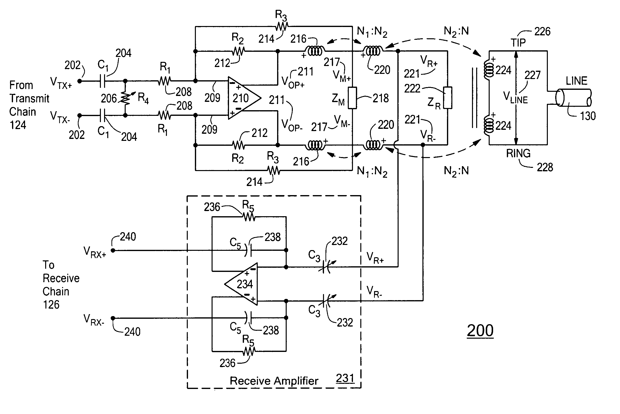
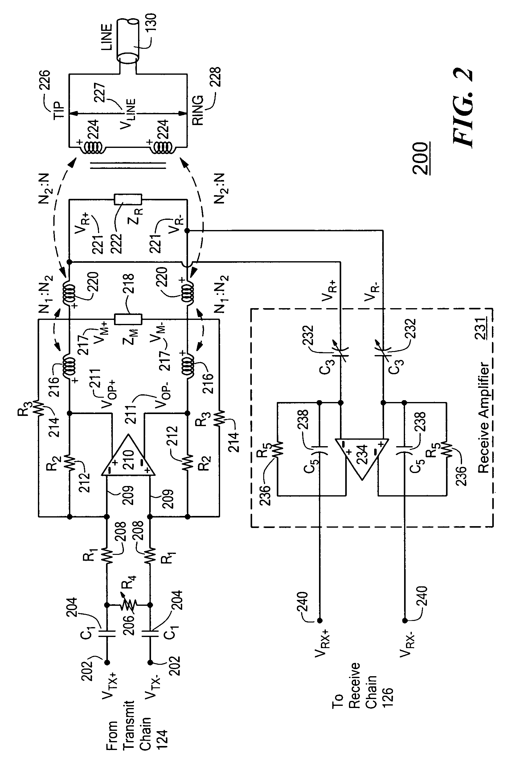
[0038]FIG. 2 is a schematic diagram showing an exemplary line interface architecture 200 for an ADSL modem front end in accordance with the present invention. The line interface 200 uses a fully-differential voltage-feedback implementation of a line driver, a single-transformer hybrid, a single matching impedance, and a receive path amplifier. The transformer uses split windings on both the primary side (i.e., the side coupled to the transmitter 124 and the receiver 126) and the secondary side (i.e., the side coupled to the line 130). On the primary side of the transformer, each half of the primary side is tapped to obtain a turns ratio of N1:N2, while each half of the secondary side of the transformer has N windings. A dual negative-feedback network (described below) boosts the small-signal impedance of the matching network 218 (ZM) to a much larger line driver output impedance in order to match the characteristic impedance of the transmission line (ZL). Matched termination of the ...

second embodiment

[0060]FIG. 4 is a schematic diagram showing an exemplary line interface architecture 400 for an ADSL modem front end in accordance with the present invention. The line interface 400 uses a fully-differential voltage-feedback implementation of a line driver, a single-transformer hybrid, a single matching impedance, and a receive path amplifier. The transformer uses split windings on both the primary side (i.e., the side coupled to the transmitter 124 and the receiver 126) and the secondary side (i.e., the side coupled to the line 130). On the primary side of the transformer, each half of the primary side is tapped to obtain a turns ratio of N1:N2, while each half of the secondary side of the transformer has N windings. A dual negative-feedback network (described below) boosts the small-signal impedance of the matching network 418 (ZM) to a much larger line driver output impedance in order to match the characteristic impedance of the transmission line (ZL). Matched termination of the ...


PUM


Abstract

A line interface performs echo cancellation without the use of a hybrid filter network and includes a transmit path having a line driver, a single matching network terminating the line, and a single transformer. The transformer uses split windings on both the primary side and the secondary (line) side. Each half of the primary side is tapped to obtain a turns ratio of N1:N2, while each half of the secondary side of the transformer has N windings. The single matching impedance is coupled in parallel between the first winding and the second winding on each half of the primary side. Either the voltage across the matching impedance or the voltage across the receive terminals is bootstrapped to the receive signal through multiple negative feedbacks. The transfer function of the line driver is shaped as a first-order high-pass filter (HPF) to reject any out-of-band noise and distortion components.

Description

FIELD OF THE INVENTION[0001]The present invention relates generally to communication systems, and more particularly to a line interface with analog echo cancellation, for example, for use in a communication device such as a digital subscriber line modem.BACKGROUND OF THE INVENTION[0002]Certain communication devices transmit and receive signals over a communication medium, such as a telephone or cable line. These communication devices typically include a transmitter and a receiver (sometimes referred to collectively as a transceiver) coupled to the communication medium through a line interface. Among other things, the line interface generally acts as the electrical interface between the transceiver and the line.[0003]In some communication devices, transmitted signals can be leaked or reflected back to the receiver so as to constitute part of the received signals. For convenience, these reflected signals are often referred to as “echoes.” Similar to a person's voice echoing off of a c...

Claims


Application Information

Patent Timeline
Patent Type & Authority Patents(United States)
IPC IPC(8): H04M1/00H04M9/00
CPCH04B3/03H04B3/12H04M3/002
Inventor CHOKSI, OJAS M.
Owner ANALOG DEVICES INC
Learn More