Small engine fuel tank with integrated evaporative controls

a fuel tank and small engine technology, applied in the direction of fuel injection apparatus, fuel feed system, non-fuel substance addition to fuel, etc., can solve the problems of engine installation, tank and fuel system design and installation, added costs, etc., and achieve the effect of simplifying the mounting of the fuel vapor emission devi

Active Publication Date: 2007-05-08
EATON INTELLIGENT POWER LTD
View PDF16 Cites 9 Cited by
  • Summary
  • Abstract
  • Description
  • Claims
  • Application Information

AI Technical Summary

Benefits of technology

[0003]The present invention provides a small engine fuel tank with integral fuel evaporative controls including a storage canister and rollover valve disposed within the tank in a manner which provides adequate control of fuel vapor emissions during periods of engine inoperation, permits purging during engine operation and thus simplifies the mounting of the fuel vapor emission devices on the engine.

Problems solved by technology

This recently imposed requirement on small engine manufacturers has created problems in installing the engines in the equipment in which they are to be used inasmuch as the equipment manufacturer commonly purchases the engine and fuel tank for installation as a subassembly during final assembly of the engine operated equipment.
Thus, for the aforesaid equipment applications the burden of providing for fuel vapor emission control has been imposed upon the small engine manufacturer and has created problems in the design and installation of the tank and fuel system for the small engines.
In particular, the requirement for a vapor storage device has been found to create problems in mounting the tank and fuel system on a small engine as a prepackaged subassembly; and, has added additional costs in providing for the storage device and the mounting and vapor conduit interconnections between the storage device and the tank.

Method used


Image

  • Small engine fuel tank with integrated evaporative controls
  • Small engine fuel tank with integrated evaporative controls
  • Small engine fuel tank with integrated evaporative controls

Examples


Embodiment Construction

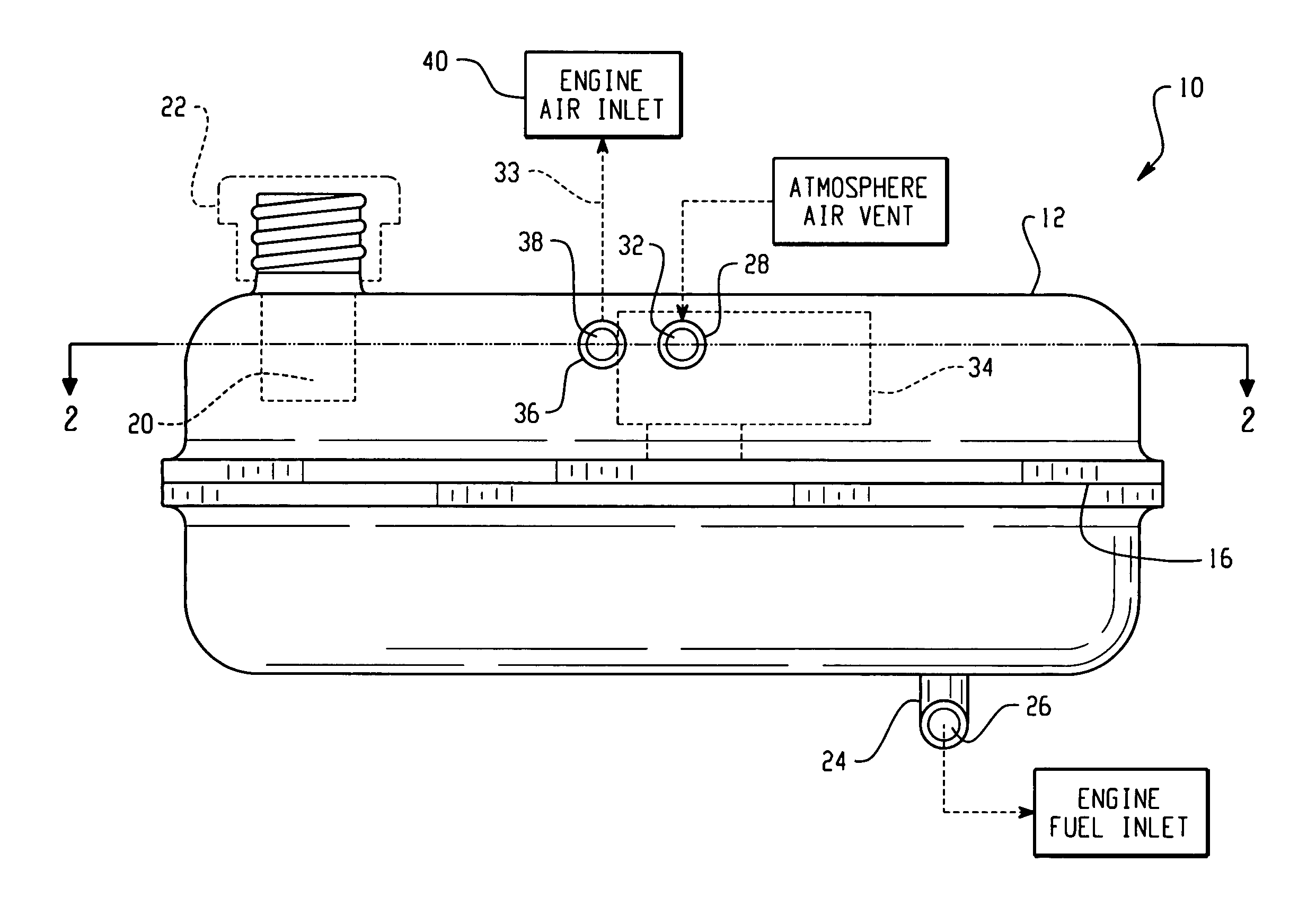
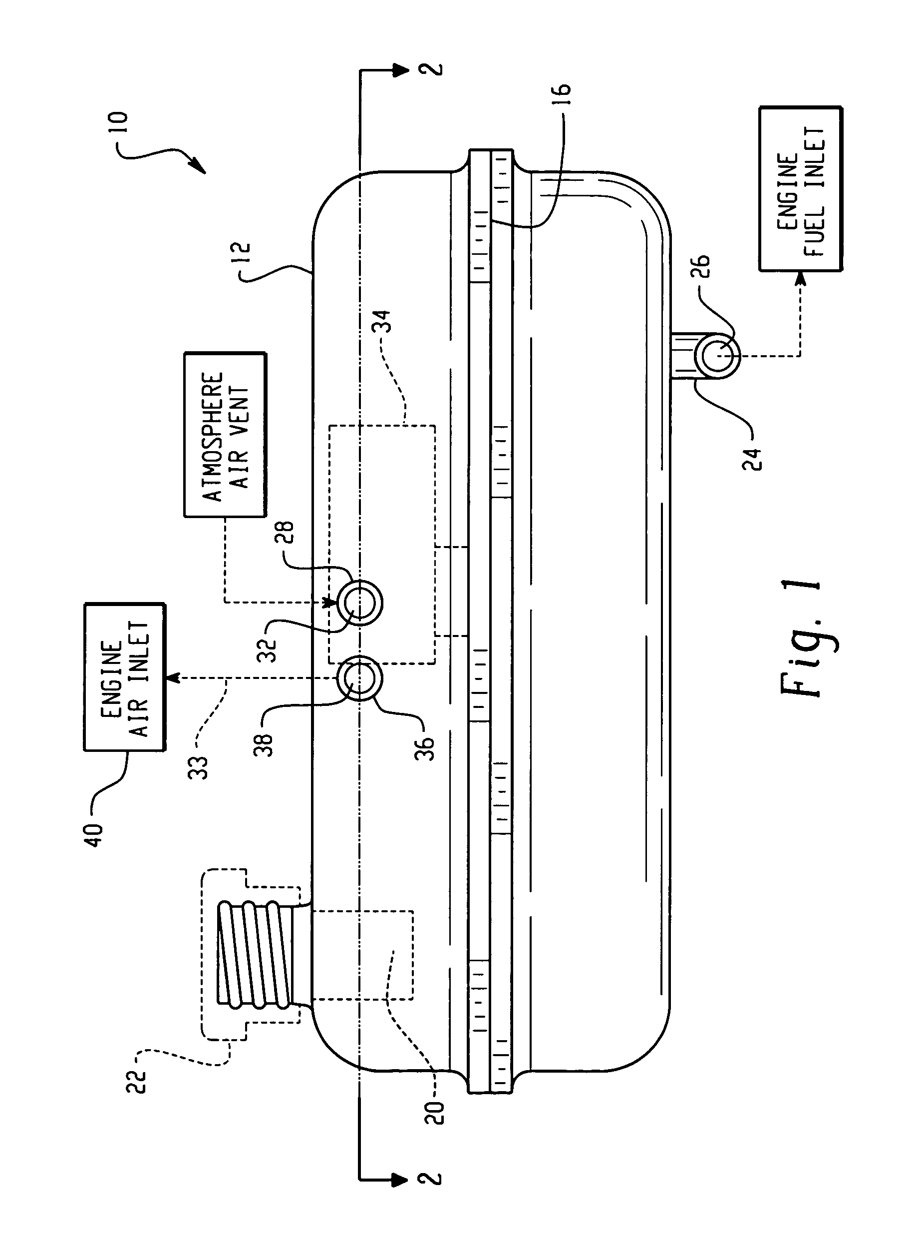
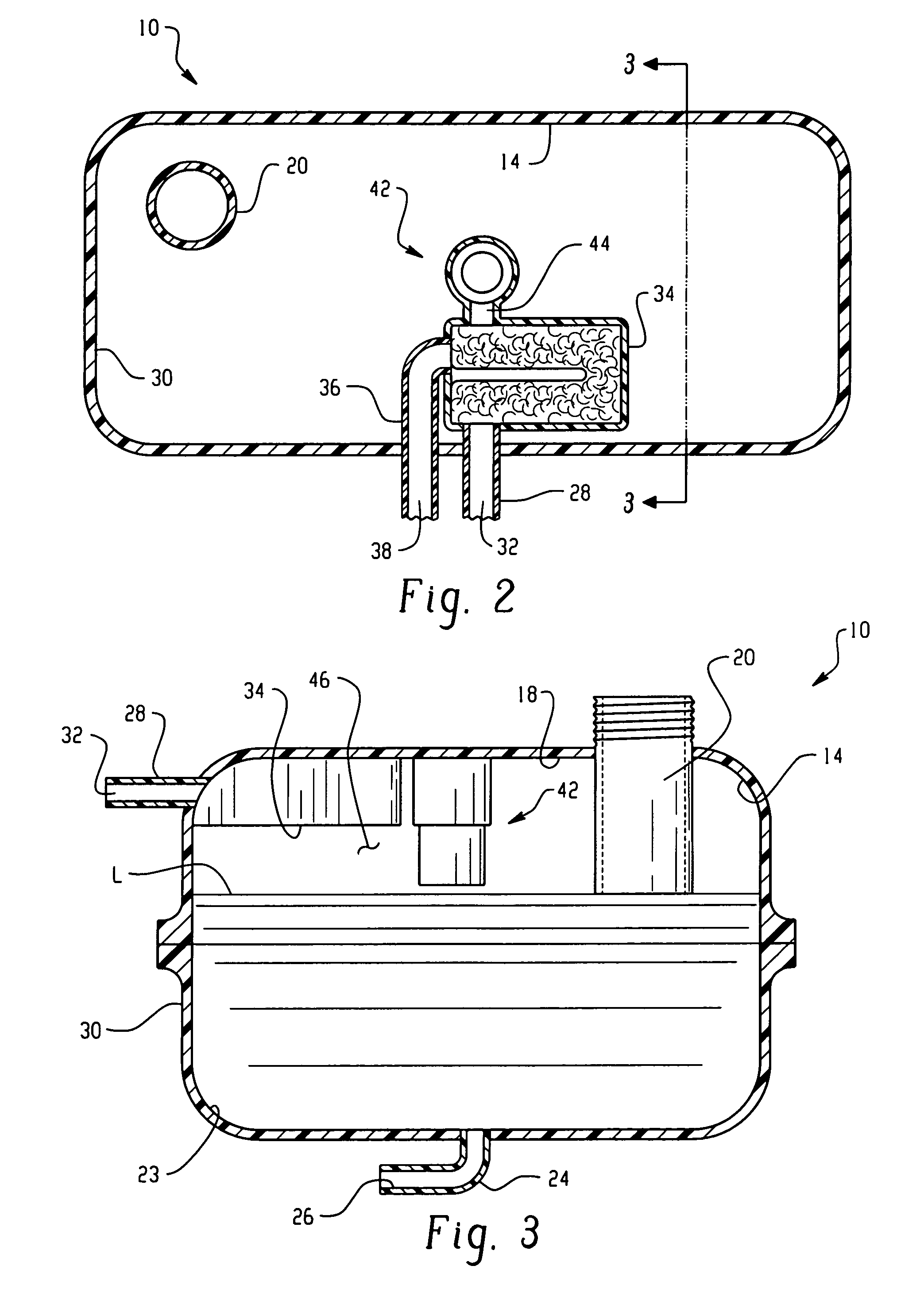
[0007]Referring to the drawings, the fuel tank assembly of the present invention is indicated generally at 10 and includes a tank 12 having wall structure 14 which may be formed conveniently by weldment about a mid-seam 16 in any manner well known in the art as, for example, by metallic or non-metallic welding as the case may be for the particular material employed for the tank.

[0008]The upper wall 18 of the tank has provided therein a filler tube 20 which may be integrally formed with the upper wall 18 and which is adapted for receiving thereover a closure cap 22 indicated in dashed outline in FIG. 1. The tube 20 extends downwardly into the interior of the tank to a desired depth for creating a vapor dome in the region beneath the upper wall 18 when the liquid level in the tank has risen to cover the lower end of tube 20.

[0009]Tank 12 has a fuel feed outlet fitting 24 provided through the lower wall on the lower wall thereof with a fuel feed passage 26 formed therein for gravity fe...


PUM


Abstract

A fuel tank assembly for small engines having a vapor storage canister disposed within the tank in the vapor dome with an atmospheric vent line to the canister through the tank wall and a canister vapor outlet line also through the tank wall. A fuel vapor vent valve is disposed in the vapor dome of the tank with the vent valve outlet connected to the canister inlet. A fuel filler tube extends through the tank wall to a desired depth to prevent vapor from escaping through the filler tube when the fuel level rises to the lower end of the filler tube and alerts the operator by rapid rise of fuel in the filler tube.

Description

BACKGROUND OF THE INVENTION[0001]The present invention relates to fuel tanks for small engines such as those employed in portable power equipment as, for example, lawn mowers and portable generator sets. Recent regulations for controlling the emission of fuel vapors have required installation of vapor storage devices to prevent escape of fuel vapors through the engine air inlet during periods when the engine is not operating and provide for purging when the engine is running. This recently imposed requirement on small engine manufacturers has created problems in installing the engines in the equipment in which they are to be used inasmuch as the equipment manufacturer commonly purchases the engine and fuel tank for installation as a subassembly during final assembly of the engine operated equipment. Thus, for the aforesaid equipment applications the burden of providing for fuel vapor emission control has been imposed upon the small engine manufacturer and has created problems in the...

Claims


Application Information

Patent Timeline
Patent Type & Authority Patents(United States)
IPC IPC(8): F02M55/02F02M25/08F02M33/02F02M37/10F02M37/20
CPCF02M25/0854F02M37/10F02M37/20
Inventor MILLS, VAUGHN K.
Owner EATON INTELLIGENT POWER LTD
Why Eureka
Try Eureka