Low acceleration sensitivity microphone

a microphone and acceleration sensitivity technology, applied in the field of low acceleration sensitivity microphones, can solve the problems of limiting factors in the design of implantable microphones, acceleration pressure is a limiting factor, etc., and achieve the effects of reducing vibration effects, reducing vibration sensitivity of microphone assemblies, and better isolation of ambient acoustic signals

Active Publication Date: 2007-05-08
COCHLEAR LIMITED
View PDF64 Cites 52 Cited by
  • Summary
  • Abstract
  • Description
  • Claims
  • Application Information

AI Technical Summary

Benefits of technology

[0011]It is possible to reduce vibration sensitivity of a microphone assembly through vibration isolation. In its simplest form, a vibration isolator is a spring (i.e., compliant member) that suspends the assembly to be isolated. The spring rate of the isolator is chosen so that the resonate frequency of the suspended microphone is much lower than the lowest frequency to be isolated, typically by a factor of five or more. While reducing the effects of vibration directly on the microphone, it will be appreciated that vibration may still cause acceleration induced pressure variations within the tissue overlying the microphone and microphone diaphragm. Therefore, such acceleration must still be accounted for to better isolate ambient acoustic signals from a commingled signal. In this regard, the inventors have further recognized the desirability of actively accounting for the effects of acceleration and have produced a microphone that exhibits low sensitivity to acceleration-induced pressures.
[0012]More specifically, the present invention utilizes an output that is indicative of acceleration acting on the microphone (e.g., an acceleration signal) to counteract and / or cancel the effects of acceleration-induced pressures in an output signal of a microphone diaphragm. Generally, the acceleration signal and the acceleration induced pressures effects in the output signal will correspond to a common source (e.g., a common vibration). Accordingly, the magnitude an / or phase of the acceleration signal acceleration induced pressure effects may be mathematically related. Counteracting and / or canceling the effect of acceleration may be done in a variety of ways, including but not limited to, pneumatically, mechanically, electrical analog, or digitally, or combinations thereof. In order to better account for the effect of acceleration on the microphone, the acceleration signal, microphone diaphragm output signal, or both may be filtered and adjusted for gain (again, including but not limited to pneumatically, mechanically, electrical analog or digitally or any combination thereof) before utilizing the acceleration signal for counteraction / cancellation. This filtering may have the effect of more closely matching the acceleration signal to the acceleration responses in the microphone output signal and thereby substantially reduce the effects of acceleration on the implanted microphone. The filter or filters may be adjustable and / or adaptive in order to allow optimal rejection of vibration for a given patient under a variety of changing conditions.
[0027]In another arrangement, the resonant frequency of the first diaphragm and / or cancellation surface may be greater than most or all of an acoustic hearing frequency range. In such an arrangement, the response of the first diaphragm and / or cancellation surface may be flatter over a greater frequency range. This may permit more easily matching outputs from these elements.
[0028]The cancellation surface may be any surface that is operative to move in response to acceleration forces applied to the microphone. In this regard, the cancellation surface may be considered an accelerometer or more generally a motion sensor. The physical configuration of this accelerometer / motion sensor (hereafter accelerometer) and the output of the accelerometer may vary. For instance, the accelerometer may include a compliantly supported mass (e.g., a proof or seismic mass). Inertial movement of the proof mass in response to acceleration forces may physically counteract the movement of the microphone diaphragm in response to acceleration.
[0029]In another arrangement, the cancellation surface may generate an electrical output (acceleration signal), which may subsequently be combined (e.g., subtracted) with an electrical microphone output signal of the first diaphragm. Use of such electrical signals may facilitate filtering of the acceleration signal of the accelerometer and / or the microphone output signal to better match, for example, the phase and / or magnitude of these signals.

Problems solved by technology

In this regard, acceleration pressure is a limiting factor in implantable microphone design.

Method used


Image

  • Low acceleration sensitivity microphone
  • Low acceleration sensitivity microphone
  • Low acceleration sensitivity microphone

Examples


Embodiment Construction

[0050]Reference will now be made to the accompanying drawings, which at least assist in illustrating the various pertinent features of the present invention. In this regard, the following description of a hearing instrument is presented for purposes of illustration and description. Furthermore, the description is not intended to limit the invention to the form disclosed herein. Consequently, variations and modifications commensurate with the following teachings, and skill and knowledge of the relevant art, are within the scope of the present invention. The embodiments described herein are further intended to explain the best modes known of practicing the invention and to enable others skilled in the art to utilize the invention in such, or other embodiments and with various modifications required by the particular application(s) or use(s) of the present invention.

Hearing Instrument System:

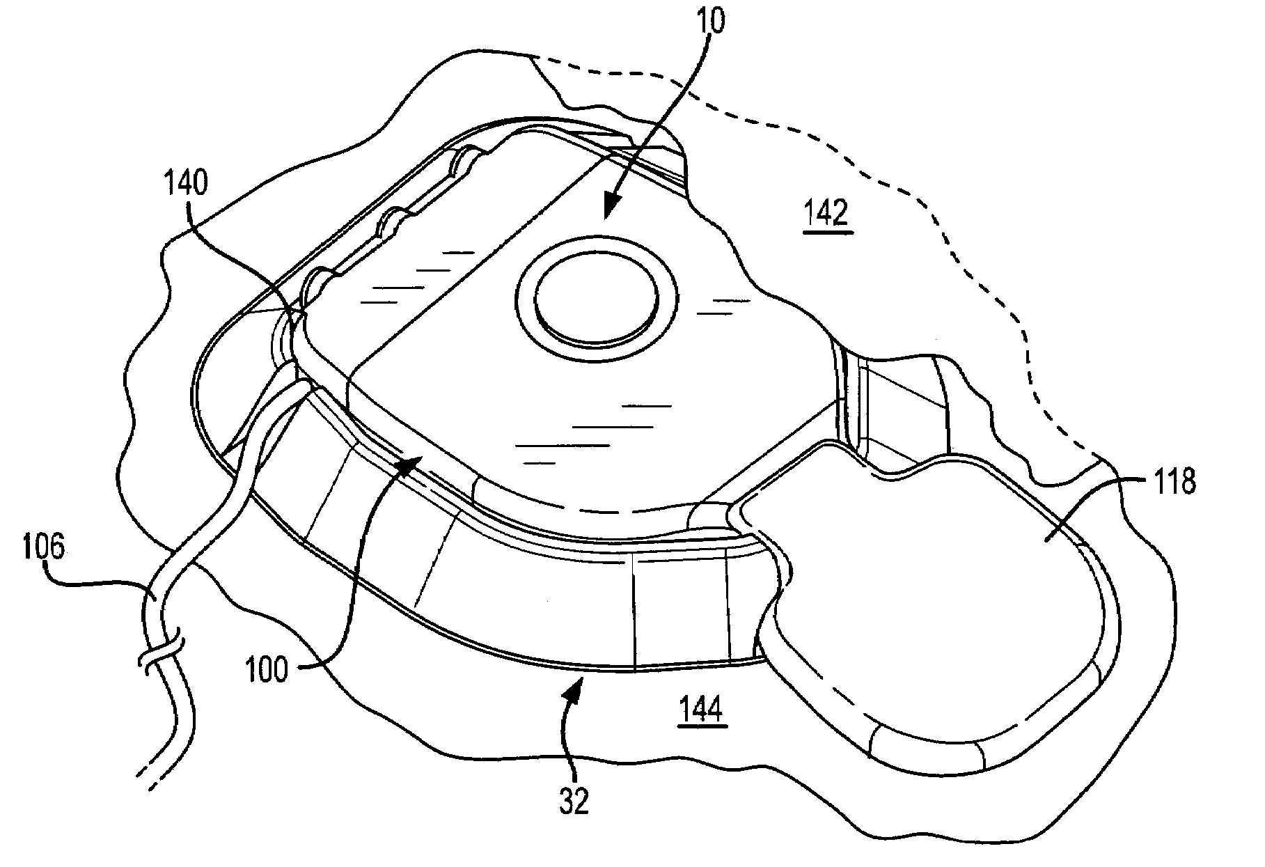
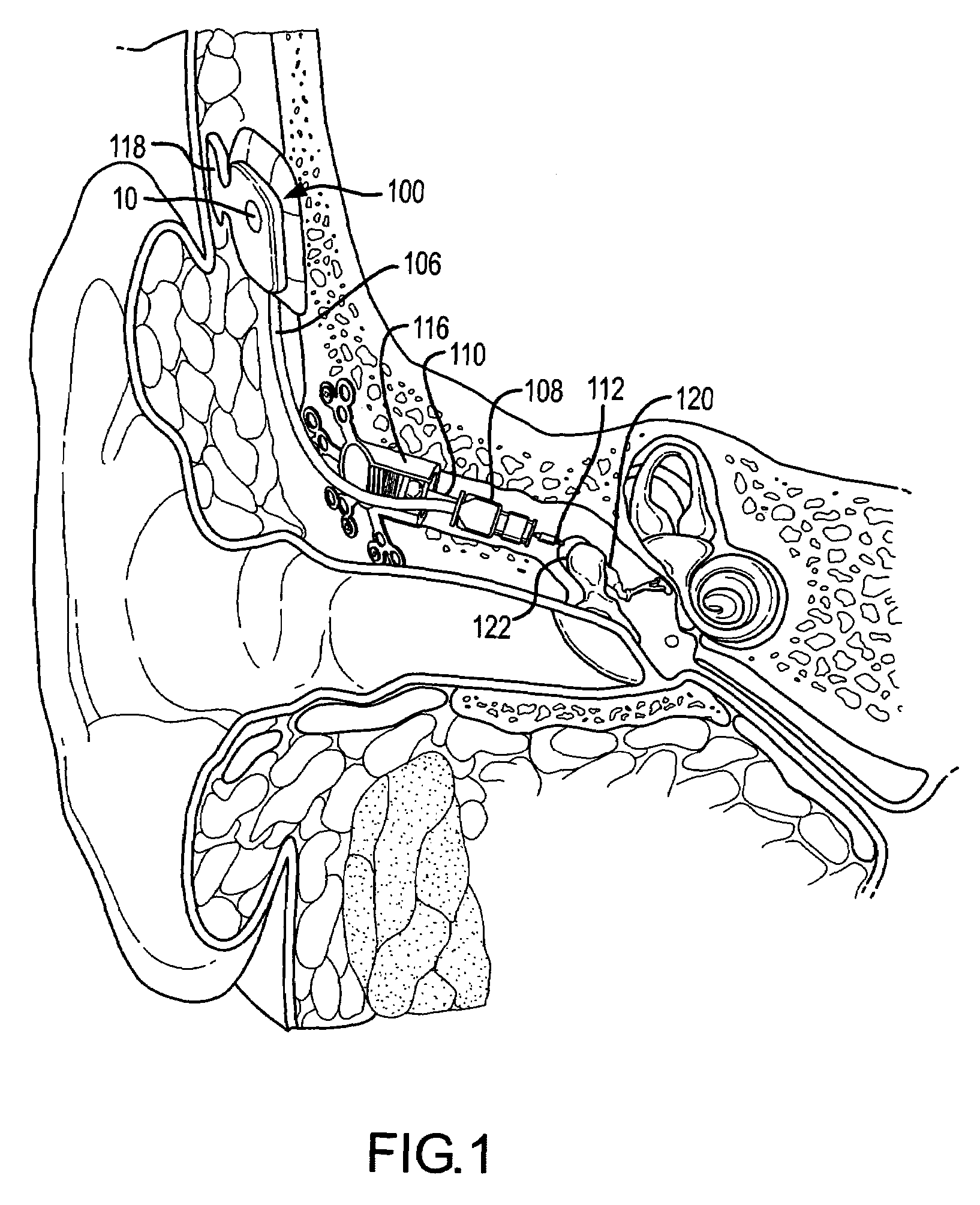
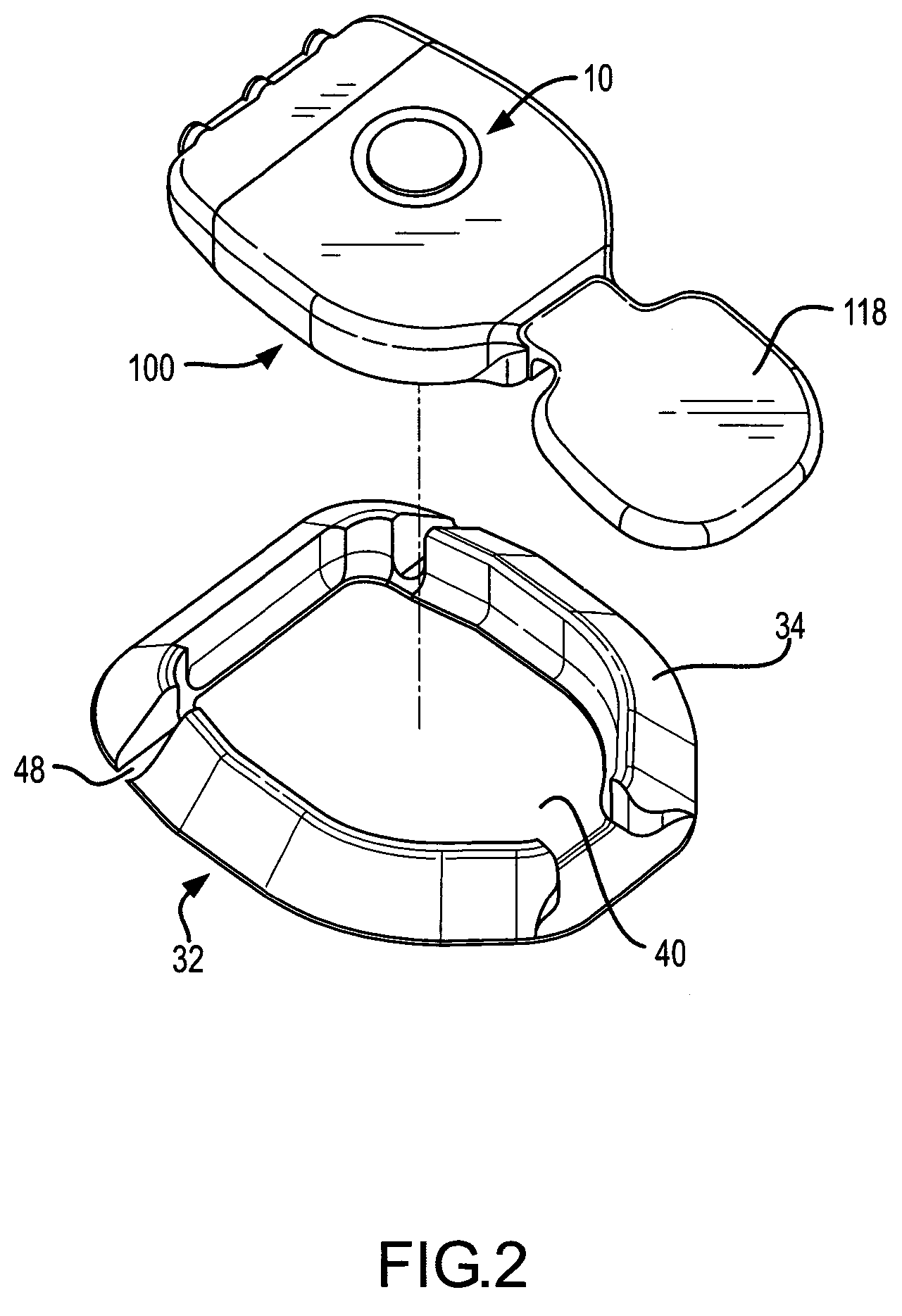
[0051]FIGS. 1–3 illustrate one application of the present invention. As illustrated, the applic...


PUM


Abstract

An implanted microphone is provided that has reduced sensitivity to vibration and attendant acceleration forces. In this regard, the microphone differentiates between the desirable and undesirable components of a transcutaneously received signal. More specifically, the present invention utilizes an output that is indicative of acceleration forces acting on the implanted microphone (e.g., an acceleration signal) to counteract and / or cancel the effects of acceleration induced pressures in an output signal of a microphone diaphragm. This may be done in a variety of ways, including but not limited to, pneumatically, mechanically, electrical analog, or digitally, or combinations thereof. In one arrangement, the generated output may be filtered to match the an acceleration response of the output signal of the microphone diaphragm such that upon removal of the motion signal from the microphone output, the remaining signal is an acoustic signal.

Description

CROSS REFERENCE TO RELATED APPLICATIONS[0001]This application claims priority under 35 U.S.C. 119 to: U.S. Provisional Application No. 60 / 558,693 entitled: “Low Acceleration Sensitivity Microphone,” having a filling date of Apr. 1, 2004; and U.S. Provisional Application No. 60 / 643,074 entitled: “Active Vibration Attenuation for Implantable Microphone,” having a filing date of Jan. 11, 2005; and claims priority under 35 U.S.C. 120 as a continuation-in-part to U.S. patent application Ser. No. 10 / 982,639 entitled “Active Vibration Attenuation for Implantable Microphone,” having a filing date of Nov. 5, 2004; the contents of each of which are incorporated herein as if set forth in full.FIELD OF THE INVENTION[0002]The present invention relates to implanted microphone assemblies, e.g. as employed in hearing aid instruments, and more particularly, to implanted microphone assemblies having reduced sensitivity to acceleration.BACKGROUND OF THE INVENTION[0003]Until recently, a large number of...

Claims


Application Information

Patent Timeline
Patent Type & Authority Patents(United States)
IPC IPC(8): H04R25/00H04R1/08
CPCH04R25/604H04R19/016H04R25/606H04R2225/67
Inventor MILLER, III, SCOTT ALLANSCHNEIDER, ROBERT EDWINBASINGER, DAVID L.ANDREWS, TRAVIS RIANWALDMANN, BERND
Owner COCHLEAR LIMITED
Why Eureka
Try Eureka