Electrical connector having an outlet end angularly disposed relative an inlet end with outer retainer ring about the outlet end and internal unidirectional conductor retainer in the inlet end

a technology of electrical connectors and connector assemblies, which is applied in the direction of electrical devices, substation/switching arrangement details, coupling device connections, etc., can solve the problems of time-consuming, difficult, and nuisance at times, and achieve the effect of easy disassembly, easy disassembly and assembly, and inherent resiliency of materials

Active Publication Date: 2007-05-08
BRIDGEPORT FITTINGS LLC
View PDF64 Cites 43 Cited by
  • Summary
  • Abstract
  • Description
  • Claims
  • Application Information

AI Technical Summary

Benefits of technology

[0013]Another object is to provide an electrical connector assembly having a connector body with a frustro-conical outer retainer ring circumscribing the outer surface of the connector body outlet end and a unidirectional wire conductor retainer associated with the inlet end of the connector for securing an electrical wire or conductor thereto without the need of any extraneous hand tools.
[0014]Another object is to provide a 90° electrical connector assembly that includes a unidirectional wire or conductor retainer extending internally of the inlet end thereof for frictionally retaining a wire conductor to the connector assembly so as to prevent any unintentional separation of a wire conductor therefrom.
[0015]Another object is to provide a 90° electrical connector assembly provided with a snap fitting retainer ring on the outlet end of the connector assembly for attaching the connector assembly to an electrical box with a snap fit and having an inner unidirectional wire conductor retainer extending into the inlet end of the connector assembly for securing a wire conductor thereto in a manner to prohibit any unintentional separation of the wire conductor from the connector assembly and whereby the inlet end is formed so as to be frictionally secured to a flexible conduit.
[0016]Another object of this invention is to provide a 90° electrical connector with a wire retainer whereby a helical wound wire conductor can be secured thereto by merely inserting the armored conductor wire into the inlet end of the electrical connector to secure the wire conductor thereto, so as to prohibit any unintentional separation of the wire conductor from the electrical connector and whereby a flexible conduit may be frictionally fitted to the inlet end.
[0017]Another object is to provide or a 90° electrical connector assembly that is relatively simple to fabricate, positive in operation, and economical to produce and sell.
[0019]The outer retaining ring is initially formed from a blank of sheet material, e.g. spring steel or the like, having a cruciform shape that includes a face portion or simply a central opening wherein the radiating arms of the cruciform blank are disposed about the face portion or central opening to define a frustro-conical ring or cup. The ring or cup so formed is provided with blanked out or die cut tangs to define outwardly bent locking tangs. The trailing edge of the frustro-conical ring provides for electrical grounding. The frustro-conical ring so formed also has a slot adapted to receive the retaining lug when the retaining ring is fitted onto the outlet end of the connector body so that the free or trailing edges of the ring define a grounding edge or tang that engages the inner periphery of the knockout hole of an electric box for effecting positive electrical continuity and grounding.

Problems solved by technology

Such known elbow or angular connector bodies having such securing means generally required the use of extraneous tools such as screwdrivers, pliers, wrenches or the like for securing of such known connector bodies or assemblies to a flexible conduit which was time consuming, a nuisance, and at times relatively difficult.

Method used


Image

  • Electrical connector having an outlet end angularly disposed relative an inlet end with outer retainer ring about the outlet end and internal unidirectional conductor retainer in the inlet end
  • Electrical connector having an outlet end angularly disposed relative an inlet end with outer retainer ring about the outlet end and internal unidirectional conductor retainer in the inlet end
  • Electrical connector having an outlet end angularly disposed relative an inlet end with outer retainer ring about the outlet end and internal unidirectional conductor retainer in the inlet end

Examples


Embodiment Construction

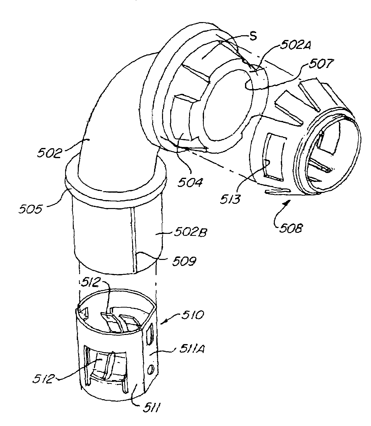
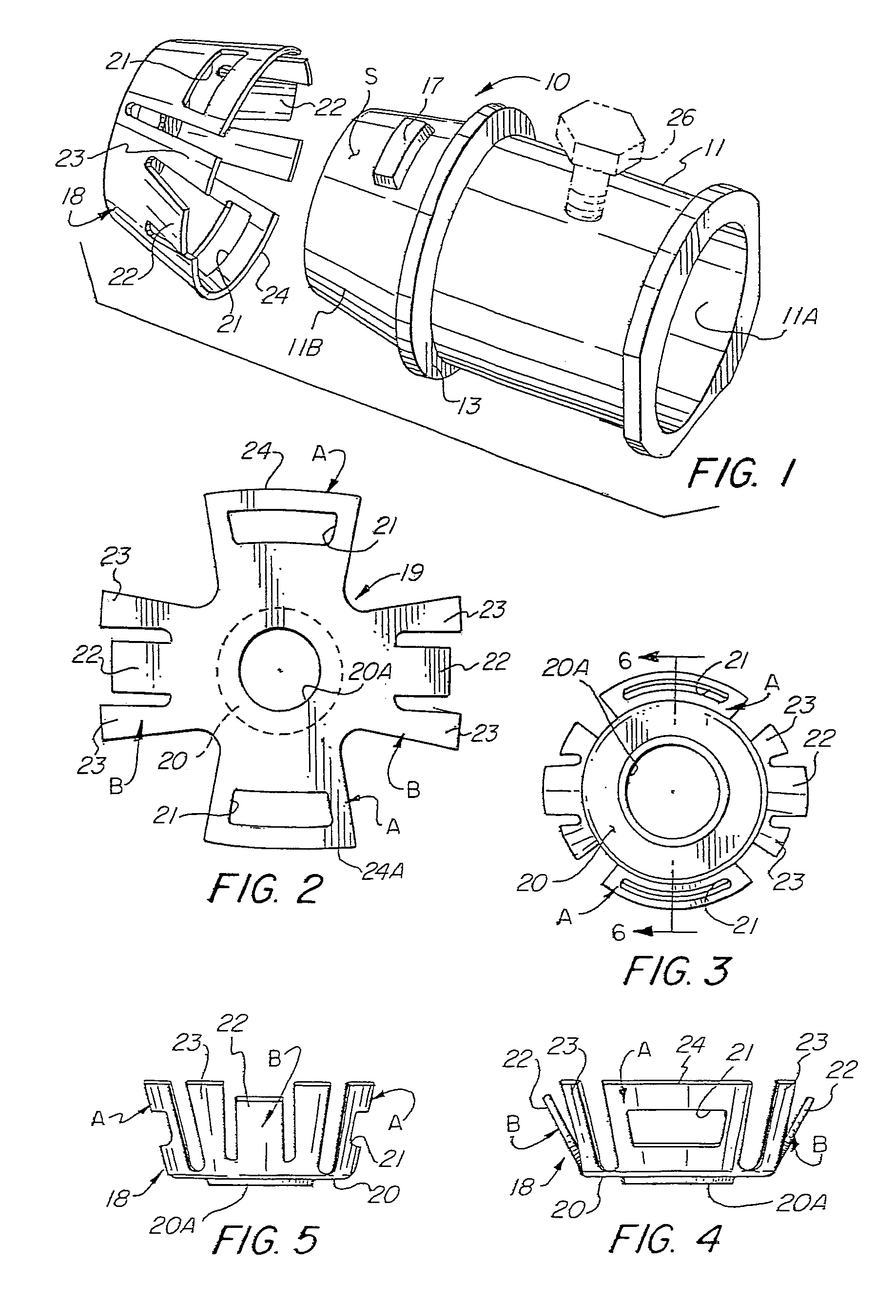
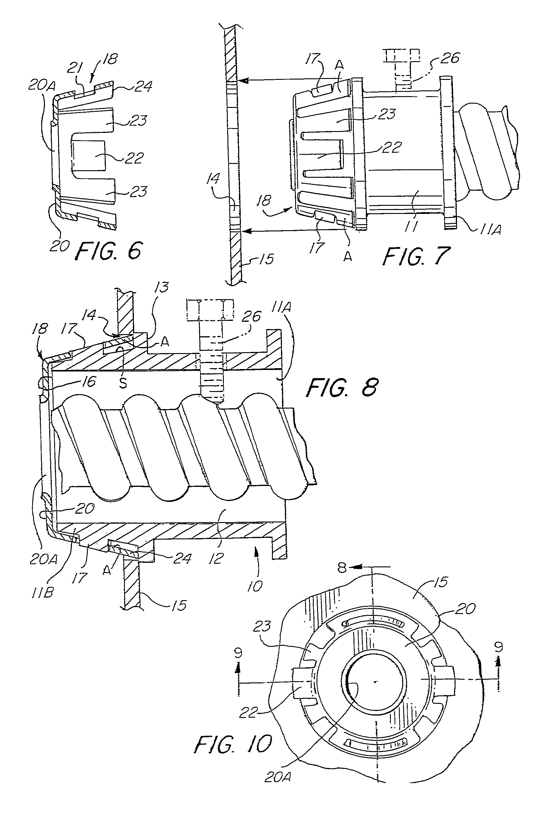
[0112]Referring to the drawings, there is shown in FIG. 1 an electrical connector assembly 10. The connector assembly 10 includes a connector body 11, which is usually formed of metal casting, e.g. zinc or other suitable metallic alloy. The connector body 11 is formed with an inlet end portion 11A and an outlet end portion 11B and having a bore 12 extending therethrough. Intermediate the connector body 11 or between the inlet end portion 11A and outlet end portion 11B there is provided a radially outwardly extending flange 13 which functions as a stop to limit the amount that the connector body 11 may be inserted through the knockout hole 14 of an electric box 15, as noted in FIG. 8.

[0113]As shown in FIGS. 1 and 8, the outer surface S of the outlet end portion 11B slopes, tapers or converges toward the outlet opening 16 whereby the outer surface S of the outlet end portion 11B has a generally frustro-conical configuration. Formed on the surface S of the outlet end portion 11B is an ...


PUM


Abstract

This disclosure is directed to electrical connectors that include a connector body having an inlet end portion and an outlet end portion and a bore extending therethrough, wherein the outlet end portion is provided with an outer surface that slopes downwardly toward the outlet opening and having a complementary sloping or frustro-conical retaining ring having locking tangs and grounding tangs for snap locking the outlet end portion to an electric box or enclosure, and a wire retainer fitted to the inlet end portion for receiving and securing a wire conductor thereto. The connector body may take several forms including a form wherein the inlet opening is angularly disposed relative to the outlet opening, with the inlet opening being formed to be press fitted onto a flexible conduit.

Description

RELATED APPLICATIONS[0001]This application is a continuation in part application of application Ser. No. 11 / 501,131 filed Aug. 8, 2006 for Electrical Connector With Outer Retainer Ring and Internal Unidirectional Conductor Retainer, which is a continuation in part application of application Ser. No. 11 / 403,099 filed Apr. 12, 2006 now U.S. Pat. No. 7,151,223 for Snap Fit Electrical Connector Assembly With Frustro Conical Retainer Ring And Internal Unidirectional Snap Fit Wire Conductor Retainer, which is a continuation in part application of application Ser. No. 11 / 400,606 filed Apr. 7, 2006 now U.S. Pat. No. 7,154,042 for Electrical Connector With Frustro Conical Snap Fit Retainer Ring Constructed To Enhance The Insertion Of The Connector Through A Knockout Hole Of An Electric Box, which is a continuation in part application of application Ser. No. 11 / 364,435 filed Feb. 28, 2006 for Snap-Fit Electrical Connector Assembly For Facilitating The Connection of the Electric Connector Asse...

Claims


Application Information

Patent Timeline
Patent Type & Authority Patents(United States)
IPC IPC(8): H02G3/06
CPCH02G3/0683H02G3/0691
Inventor KIELY, KENNETH M.AURAY, DELBERT
Owner BRIDGEPORT FITTINGS LLC
Why Eureka
Try Eureka