Clip-on electrical conduit connector

a technology of electrical conduit and clip-on connector, which is applied in the direction of insulated conductors, cables, conductors, etc., can solve the problems of disconnector loss, time and cost savings realized by pre-assembling whips, and not recovered

Inactive Publication Date: 2007-05-22
INT METAL HOSE
View PDF10 Cites 19 Cited by
  • Summary
  • Abstract
  • Description
  • Claims
  • Application Information

AI Technical Summary

Benefits of technology

[0029]In another embodiment of the instant invention, the conduit may be inserted into the conduit engagement portion by applying pressure to the conduit exterior surface, forcing the conduit through the transverse locking gap. The transverse locking feature may prevent unintentional withdrawal of the conduit in a direction substantially perpendicular to the central axis. The longitudinal locking projection may prevent unintentional withdrawal of the conduit in a direction substantially parallel to the central axis.

Problems solved by technology

At least one problem arises when the snap-in connector is used.
In a worst case situation, the connector is lost, the connector having fallen off of the conduit during transport, and is not recovered.
In either case, at a minimum, the time and cost savings realized by preassembling the whip is lost during transportation to the final installation location.
Another problem with existing snap-in connectors, referred to above, is that the connectors are difficult to install.
Occasionally, however, the tool will slip from the connector potentially resulting in a painful hand injury.
Another limitation with the existing connectors is that they do not accept a variety of conduit diameters.
Those skilled in the art will attest that creating and maintaining a large inventory of different sized connectors is time consuming and costly.
They are relatively expensive to manufacture due to their many components which must be separately manufactured and then assembled, often negating any benefit of their being able to accommodate different diameter conduit.
Using these multi-component connectors is labor intensive as there are multiple steps in inserting and securing the conduit.
Contractors and others are oftentimes in difficult working environments such as on ladders, scaffolding, in cold weather, etc.
Locknuts are dropped, cross threaded, and so on, making these assembly operations highly troublesome.

Method used


Image

  • Clip-on electrical conduit connector
  • Clip-on electrical conduit connector
  • Clip-on electrical conduit connector

Examples


Embodiment Construction

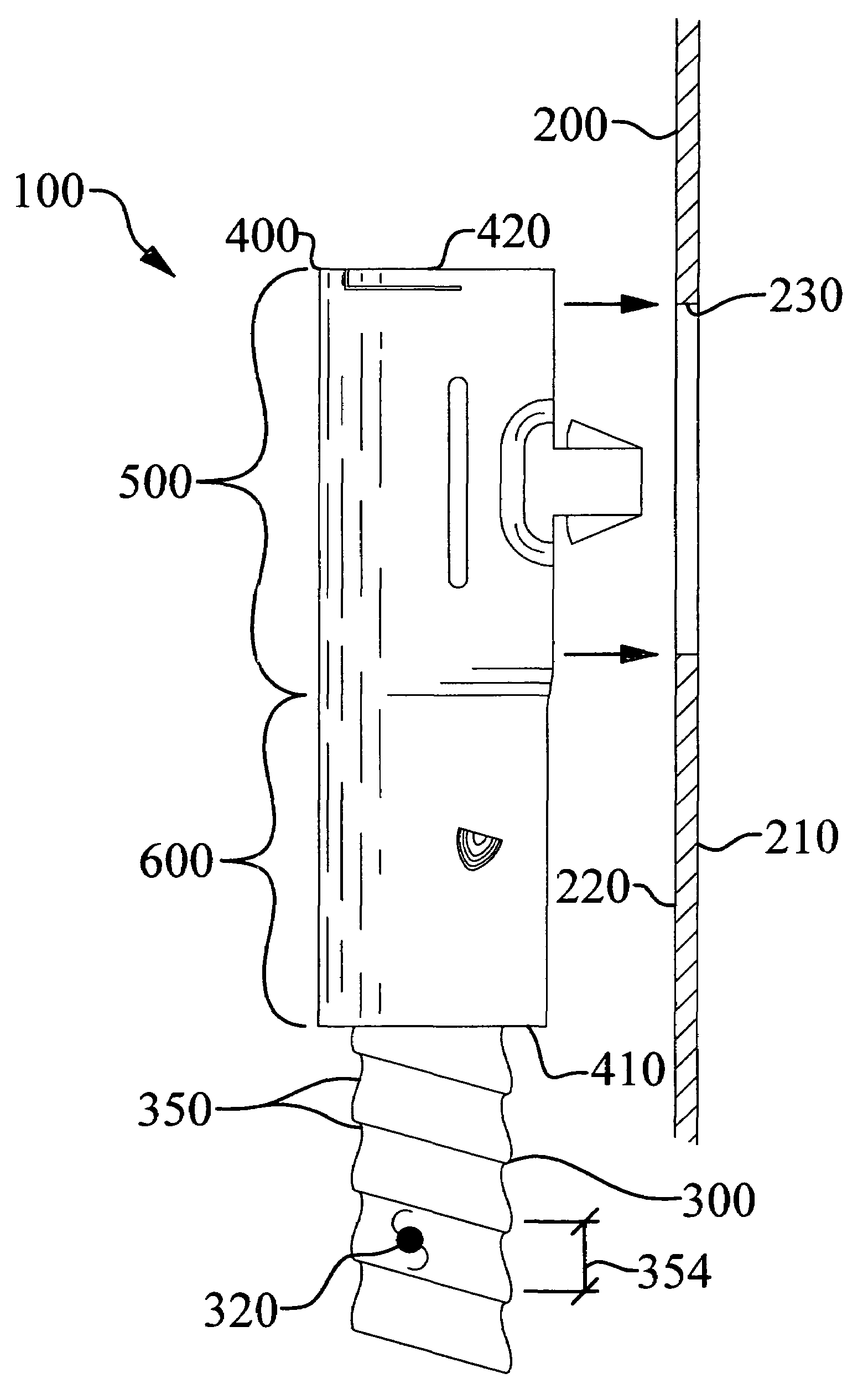
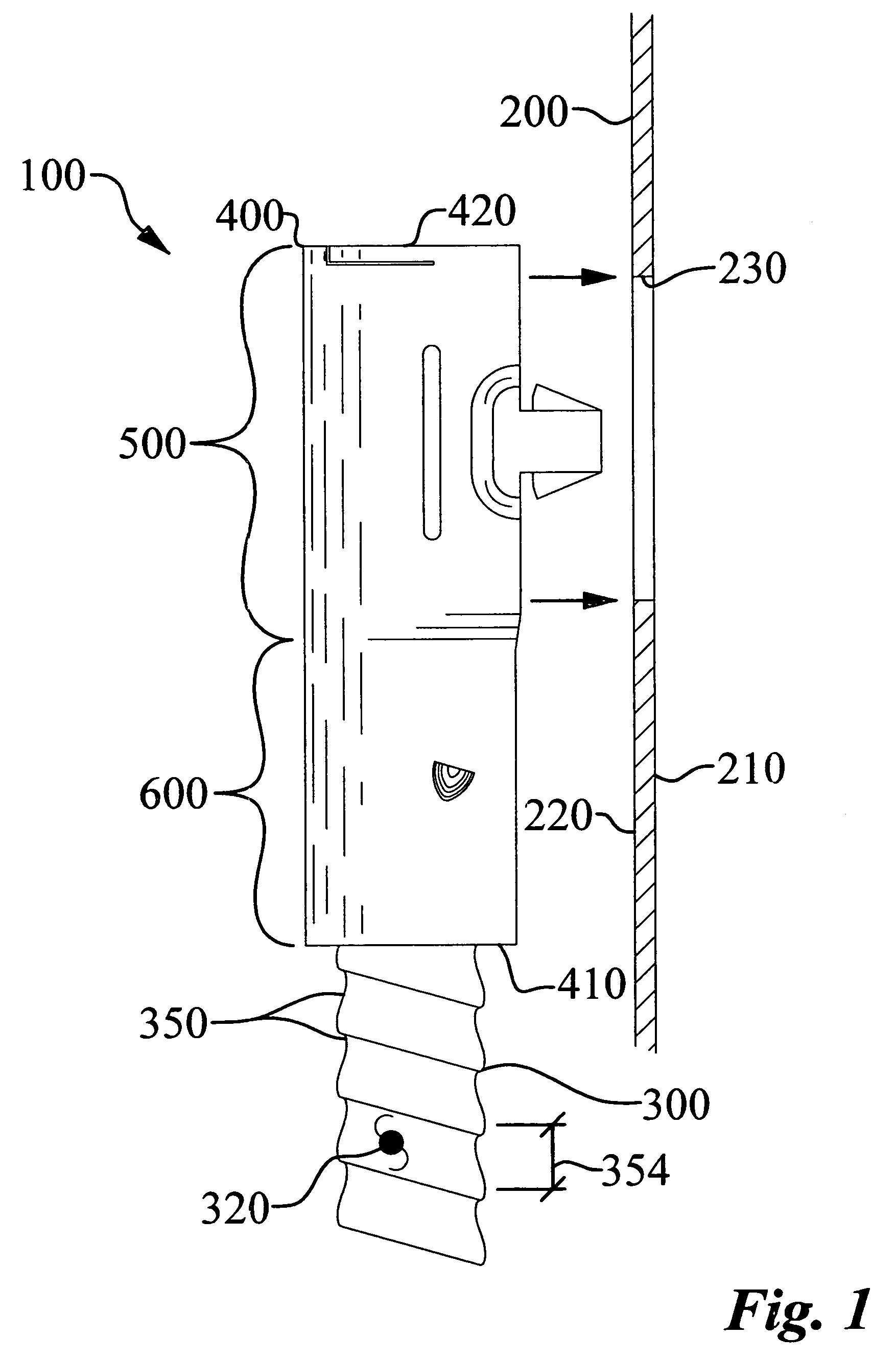
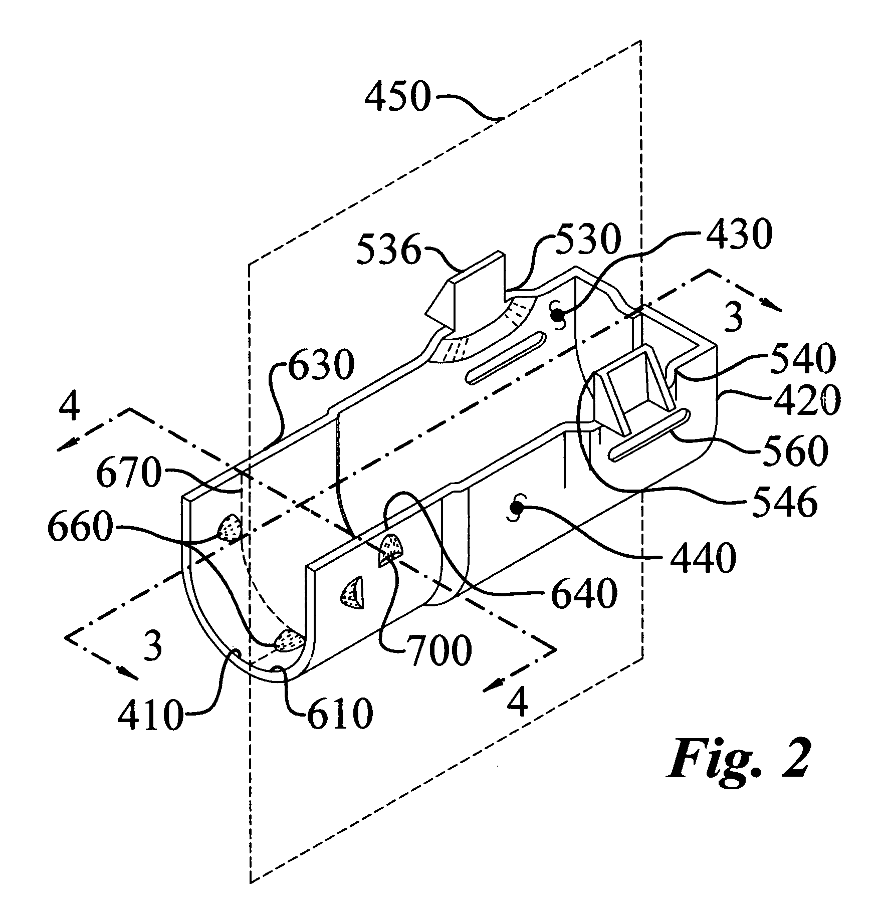
[0050]The clip-on electrical conduit connector (100) of the instant invention enables a significant advance in the state of the art. The preferred embodiments of the device accomplish this by new and novel arrangements of elements and methods that are configured in unique and novel ways and which demonstrate previously unavailable but preferred and desirable capabilities. The detailed description set forth below in connection with the drawings is intended merely as a description of the present embodiments of the invention, and is not intended to represent the only form in which the present invention may be constructed or utilized. The description sets forth the designs, functions, means, and methods of implementing the invention in connection with the illustrated embodiments. It is to be understood, however, that the same or equivalent functions and features may be accomplished by different embodiments that are also intended to be encompassed within the spirit and scope of the inven...


PUM


Abstract

A clip-on electrical conduit connector is designed to clip onto conduit for connection to junction boxes. The connector incorporates a junction box engagement portion, a conduit engagement portion, and a conduit stop. The junction box engagement portion includes a pair of attachment prongs and a grip enhancing feature. The conduit engagement portion includes two sides formed with a base, a longitudinal locking projection, and a transverse locking feature. The longitudinal locking projection prevents the conduit from being unintentionally withdrawn from the conduit engagement portion. The transverse locking feature includes a transverse locking gap for preventing unintentional withdrawal of the conduit in a transverse direction from the conduit engagement portion. Prior to final installation, the conduit is forcibly inserted into the conduit engagement portion by squeezing the conduit through the transverse locking gap or by threading the conduit into the conduit engagement portion.

Description

TECHNICAL FIELD[0001]The instant invention relates to fittings for connecting electrical conduit to junction boxes, outlet boxes, or other enclosures, and, more particularly, to an electrical conduit connector with a conduit engagement portion and a box engagement portion that quickly clips on conduit and subsequently releasably attaches to a junction box.BACKGROUND OF THE INVENTION[0002]The most common use for electrical conduit connectors is to facilitate the connection of conduit to a junction box. The junction box can be a variety of electrical enclosures such as an outlet box, transformer enclosure, circuit panel, lighting fixture—the list is nearly endless. There are many types of electrical conduit connectors. One type is used to make “snap-in,” 90 degree connections to junction boxes. The snap-in connectors do not have a locknut. Thus, during final installation, the snap-in connectors allow the electrician to quickly complete installation. The snap-in connectors are snapped ...

Claims


Application Information

Patent Timeline
Patent Type & Authority Patents(United States)
IPC IPC(8): H02G3/18
CPCH02G3/0691H02G3/263
Inventor SHEEHAN, ROBERT K.WITSMAN, JR., WAYNE E.
Owner INT METAL HOSE
Why Eureka
Try Eureka