Girder tiedown

a technology of girders and tie-downs, which is applied in the direction of rod connections, furniture parts, manufacturing tools, etc., can solve the problems of difficult attachment of heavy-duty connectors, insufficient resistance of conventional light-gauge connectors, and significant accumulation of forces in the girder. achieve the effect of easy and convenient assembly

Active Publication Date: 2006-03-23
SIMPSON STRONG TIE
View PDF54 Cites 21 Cited by
  • Summary
  • Abstract
  • Description
  • Claims
  • Application Information

AI Technical Summary

Benefits of technology

[0004] An object of the present invention is to provide a pin connection that prevents inadvertent separation of the cap and the side attachment member. This object is achieved by providing a pin connection with a pin opening in either the cap or the first side attachment member, or both, and a pin that passes through the pin opening or openings, the pin having one or more restraint extensions that extend beyond the circumference of the pin opening or openings, preventing the pin from withdrawing from the pin opening or openings. In some embodiments, this is achieved by forming the restraint extensions with one or more lobes that extend beyond the body of the pin and the pin opening.
[0012] An object of the present invention is to provide a secure connection between the connector and the supporting structural member. This is achieved by forming the side attachment member with fastener openings and passing fasteners through the openings and into the supporting structural member.
[0015] An object of the present invention is to provide a connector that is corrosion resistant. This is achieved by forming the connector from galvanized steel and, when the connector includes welding, painting the connector.
[0018] An object of the present invention is to provide a connector that has side attachment members that are simple, strong and lightweight. In some embodiments, this is achieved by forming the side attachment member by bending a V-shaped length of steel in half to form a two-ply substantially planar attachment portion and a connection portion that joins the plies at the point where the two legs of the V join.
[0021] In the first basic preferred form of the present invention, the pin is a post that is connected to, or part of, either the cap or side attachment member. There is a matching pin opening in the opposed cap or side attachment member, through which the post passes, forming a hinge. The preferred form of this pin connection permits the cap and side members to be separated from each other.
[0023] Another object of the present invention is to provide an unadjustable girder tiedown that can be made easily and at low cost on automated machinery without welding or painting and that can be directly attached to the supporting and supported structural members without the use of a cap.

Problems solved by technology

Often the accumulated forces transferred into the girder can be significant, so much that conventional light gauge connectors do not adequately resist the high uplift forces in the member and as such heavy duty connectors are required to be attached to these girders.
Attachment of these heavy duty connectors can be challenging in areas of the country which use concrete or masonry walls because many products are installed to the top of the wall system.
This poses problems particularly when products are installed after the framing is complete, which is a common occurrence.

Method used


Image

  • Girder tiedown
  • Girder tiedown
  • Girder tiedown

Examples


first preferred embodiment

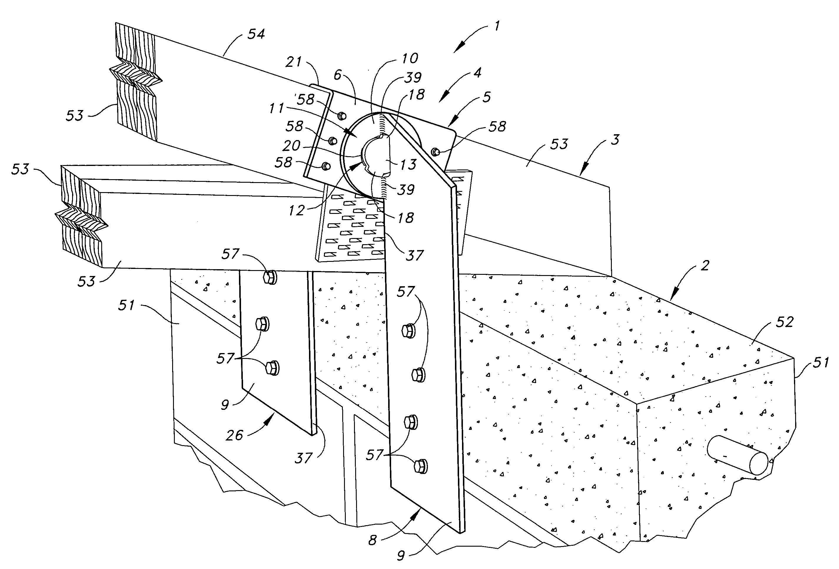
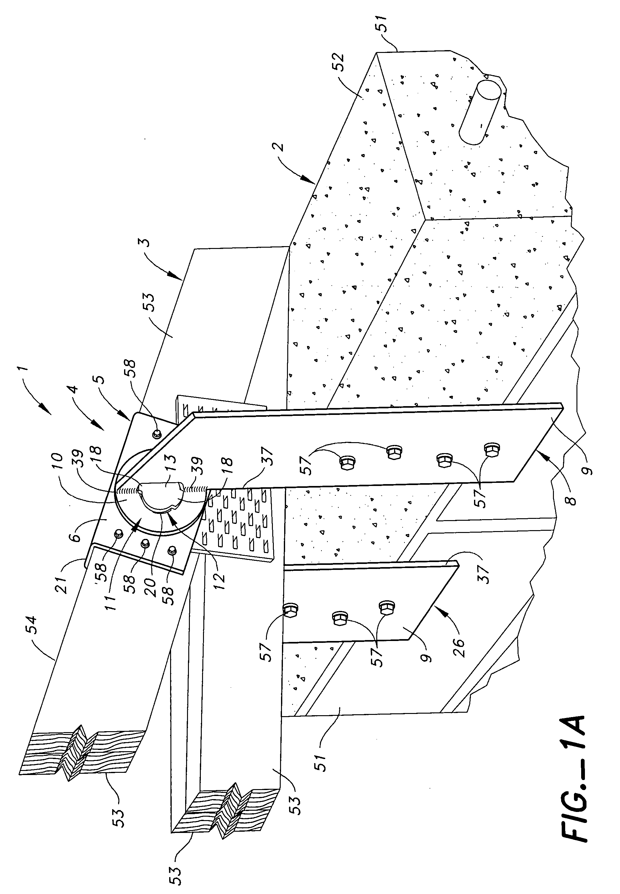
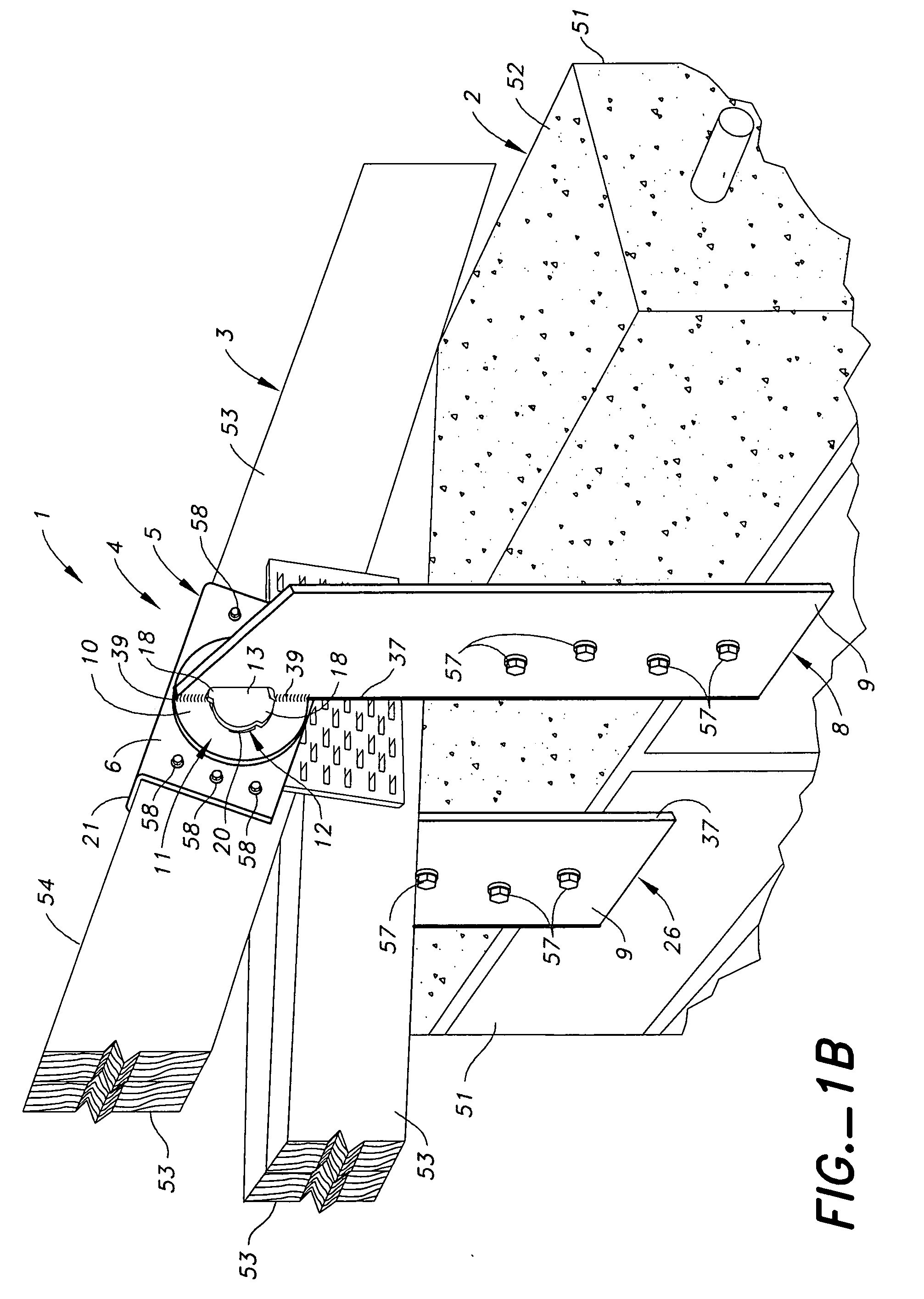
[0092] In the first preferred embodiment, the first pin 13 is fixedly attached to the other of the cap 5 and the first side attachment member 8 that does not have a first pin opening 12. Preferably, as shown in FIG. 1A, the first pin 13 is fixedly attached to the cap 5 and the first pin opening 12 is in the first side attachment member 8.

[0093] Preferably, the first restraint extension 18 is one or more lobes 18 that extend beyond the circumference 15 of the body 14 and the circumference 19 of the first pin opening 12. Preferably, the first pin opening 12 has one or more open lobes 20 that extend beyond the circumference 19 of the first pin opening 12. Preferably, the fixedly attached first pin 13 is inserted through the first pin opening 12 in an orientation that permits the one or more lobes 18 on the first pin 13 to pass through the one or more open lobes 20 of the first pin opening 12, and the cap 5 and the first side attachment member 8 are then rotated on the first pin connec...

second preferred embodiment

[0102] In the second preferred embodiment, the first pin 13 is fixedly attached to the first side attachment member 8 and the first pin opening 12 is in the cap 5. This particular arrangement, according to which the first pin 13 is fixedly attached to the first side attachment member 8, is similar to fixedly attaching the first pin 13 to the cap 5 and is, therefore, not shown in the drawings. This is less preferred than attaching the first pin 13 to the cap member 5, but it would be a functional alternative. As in the first preferred embodiment, and the first restraint extension 18 is one or more lobes 18 that extend beyond the circumference 15 of the body 14 and the circumference 19 of the first pin opening 12, and the first pin opening 12 has one or more open lobes 20 that extend beyond the circumference 19 of the first pin opening 12. The fixedly attached first pin 13 is inserted through the first pin opening 12 in an orientation that permits the one or more lobes 18 on the first...

third preferred embodiment

[0105] The third preferred embodiment is essentially the same as the first preferred embodiment, except that it is double-sided. It is always preferable that the connection of the present invention be double-sided because a single-sided connection is weaker than its double-sided counterpart. It is shown FIGS. 1A-1D and 10. In it, the cap 5 additionally comprises a second substantially planar side attachment portion 22 that interfaces with the supported structural member 3. The connector 4 additionally comprises a second side attachment member 26 comprising a substantially planar attachment portion 9 that interfaces with and is fastened to the supporting structural member 2, and a connection portion 10 that is positioned alongside the first substantially planar attachment portion 6 of the cap 5, and a second pin connection 29 that enables rotation between the second side attachment member 26 and the cap 5.

[0106] The cap 5 further comprises a second substantially planar side attachme...


PUM


Abstract

An adjustable connector is provided for connecting an elongate substantially vertical supporting structural member and an elongate generally horizontal supported structural member. The connector is provided with a side attachment member that attaches to an elongate substantially vertical supporting structural member and a cap that attaches to the elongate generally horizontal supported structural member, with a pin connection that enables rotation between the cap and the side attachment member. An unadjustable connector is also provided for connecting an elongate substantially vertical supporting structural member and an elongate generally horizontal supported structural member. The connector is provided with a side attachment member that can attach directly to an elongate substantially vertical supporting structural member and the elongate generally horizontal supported structural member.

Description

[0001] The present application is a continuation-in-part of Ser. No. 10 / 912,260, filed Aug. 4, 2004.BACKGROUND OF THE INVENTION [0002] The roof members of building structures, particularly those located in high wind areas, are often tied down to the supporting wall system to resist the uplift forces caused by winds blowing into, over, and around the structure. Conventionally, these members are tied down to the walls with simple light gauge steel brackets and / or straps which attach to the sides and tops of the roof members and the wall system. The connectors are fastened to the roof and wood wall members with nails or wood screws. The connectors are fastened to concrete or masonry walls with masonry screws, epoxied rods, or are simply embedded into the substrate during construction of the walls. Often the roof is configured such that multiple roof members are supported on one end by the wall and on the other end by a single roof member, commonly referred to as a girder. Each of the r...

Claims


Application Information

Patent Timeline
Patent Type & Authority Applications(United States)
IPC IPC(8): E04B7/02E04B1/26E04B7/04
CPCE04B7/045Y10S403/15Y10T403/4605E04B2001/2616F16B2200/503F16B9/058F16B9/052
Inventor GILSTRAP, JEREMYLIN, JIN-JIEGRAY, DANIEL M.
Owner SIMPSON STRONG TIE
Why Eureka
Try Eureka