Current power generator

a current power generator and generator technology, applied in the direction of electric generator control, machines/engines, mechanical equipment, etc., can solve the problem of disclosing such devices

Active Publication Date: 2007-05-08
GEHRING DONALD HOLLIS
View PDF26 Cites 80 Cited by
  • Summary
  • Abstract
  • Description
  • Claims
  • Application Information

AI Technical Summary

Problems solved by technology

None of the above identified devices disclose such a device.

Method used


Image

  • Current power generator
  • Current power generator
  • Current power generator

Examples


Embodiment Construction

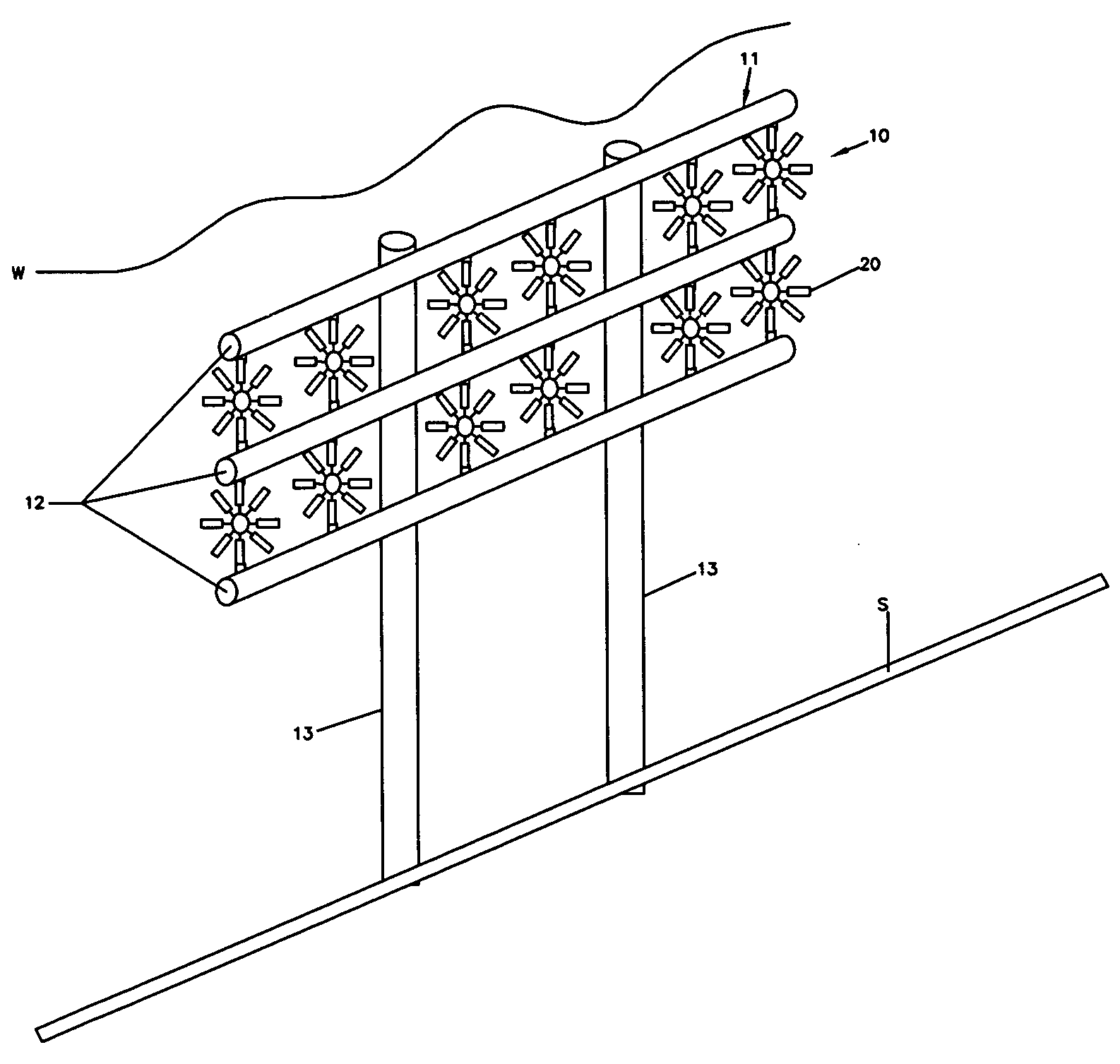
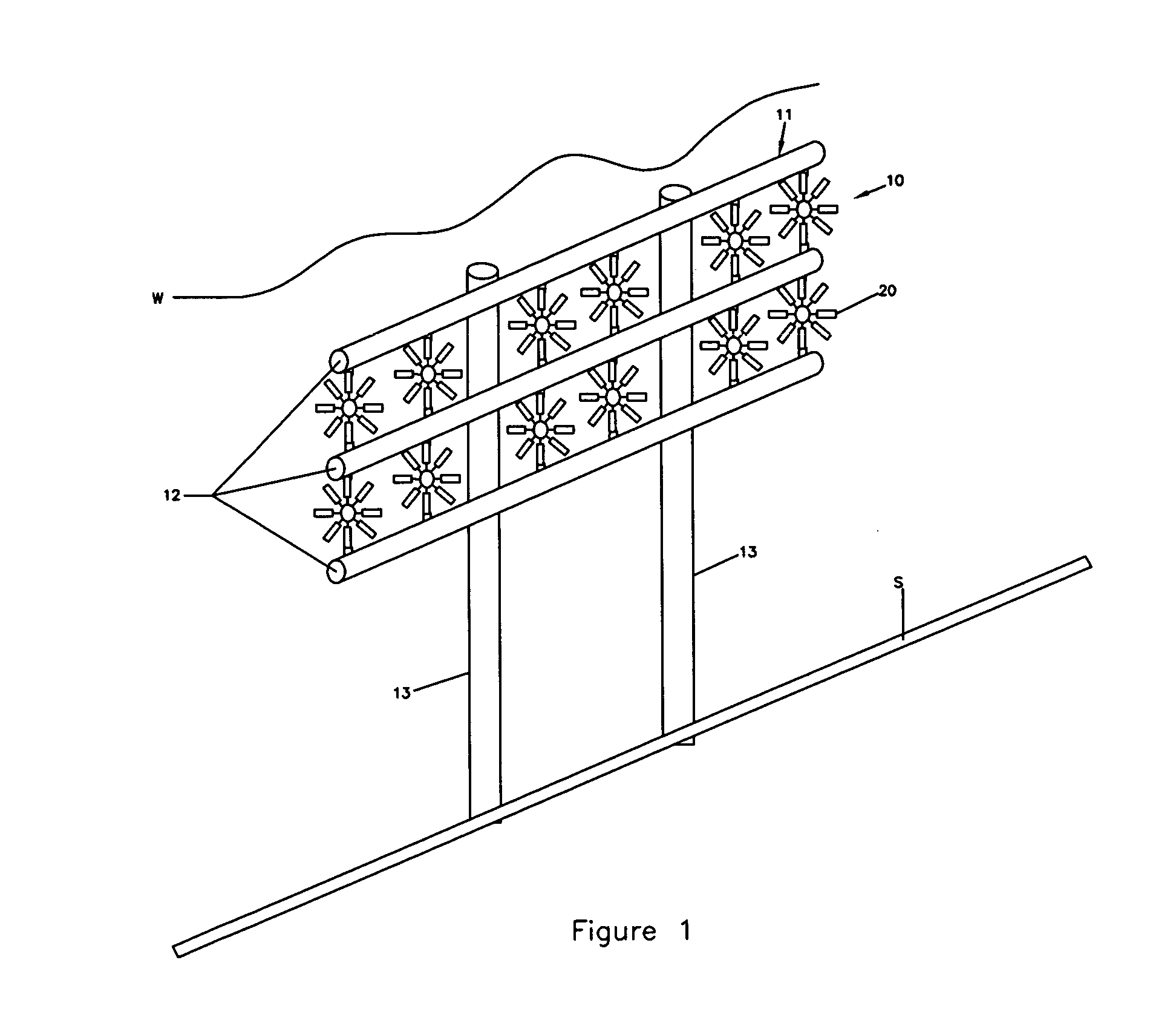
[0031]Referring now to the drawings, wherein like reference numerals refer to the same components across the several views and in particular to FIG. 1, a current power generator 10 is shown. The current power generator 10 includes a support frame 11 and a plurality of current generators 20.

[0032]The support frame 11 includes horizontal support members 12 and vertical support members 13. The vertical support members 13 are mounted at a first end to the seabed S and extend generally upward from the seabed S to a second end. Mounted proximate to the second end of the vertical support members 13 are the horizontal support members 12. In a preferred embodiment of the present invention, the horizontal support members 12 are mounted generally perpendicularly to the vertical support members 13, however, the horizontal support members 12 may be attached in any way known to one of ordinary skill in the art. In a preferred embodiment, the support frame 10 is beneath the surface line W.

[0033]Re...


PUM


Abstract

A current power generator includes a vertical support member mounted to the seabed and horizontal support members mounted to the vertical support member. Generators are mounted between the horizontal support members. A rotatable shaft is operatively connected to each of the generators such that when the shaft rotates, the generator generates electricity. Blades mounted to the shaft are capable of rotation in response to water current. The generators are pivotal relative to the horizontal support members in response to changing current flow direction.

Description

FIELD OF THE INVENTION[0001]The present invention relates to alternative energy generation sources, and in particular to a current power generator.BACKGROUND OF THE INVENTION[0002]As the demand for energy increases in both the developed and developing world, mankind turns to new and alternative sources of generating power. For example, geothermal, wind, solar, and hydroelectric sources are widely explored to help assuage the ever increasing demand for energy. To address this need, a variety of energy generating devices have been introduced.[0003]U.S. Pat. No. 6,531,788 discloses a submersible generating plant for producing electricity from ocean currents. The apparatus consists of two counter-rotating, rear-facing turbines with a plurality of rotor blades extending radially outward from two separate horizontal axis that convey the kinetic energy from the two side-by-side turbine rotors through separate gearboxes to separate generators that are housed in two watertight nacelles that ...

Claims


Application Information

Patent Timeline
Patent Type & Authority Patents(United States)
IPC IPC(8): F03B13/10
CPCF03B17/061F05B2210/16F05B2210/18F05B2240/40F05B2240/90F05B2240/95F05B2240/97Y02E10/28Y02E10/30Y02E10/20
Inventor GEHRING, DONALD HOLLIS
Owner GEHRING DONALD HOLLIS
Why Eureka
Try Eureka