Method of surveilling internet communication

a technology of internet communication and surveillance method, applied in the direction of digital transmission, data switching network, instruments, etc., can solve the problems of not enabling complete “tapping”, clearview system does not allow monitoring of data transferred between two nodes, and the solution is limited to tracking the activities of identified users

Inactive Publication Date: 2007-05-08
CREDIT SUISSE AS ADMINISTATIVE AGENT +1
View PDF7 Cites 112 Cited by
  • Summary
  • Abstract
  • Description
  • Claims
  • Application Information

AI Technical Summary

Benefits of technology

[0016]It is a further object of the invention to provide a tapping methodology enabling network

Problems solved by technology

Thus, the Clearview system does not allow monitoring of data transferred between two nodes In the network With regard to contents or characteristics.
This system is restricted to history analyze of user activities and does not enable complete “tapping” of all user activities and full simulation of the users surfing activity.
Three major problem

Method used


Image

  • Method of surveilling internet communication
  • Method of surveilling internet communication
  • Method of surveilling internet communication

Examples


Embodiment Construction

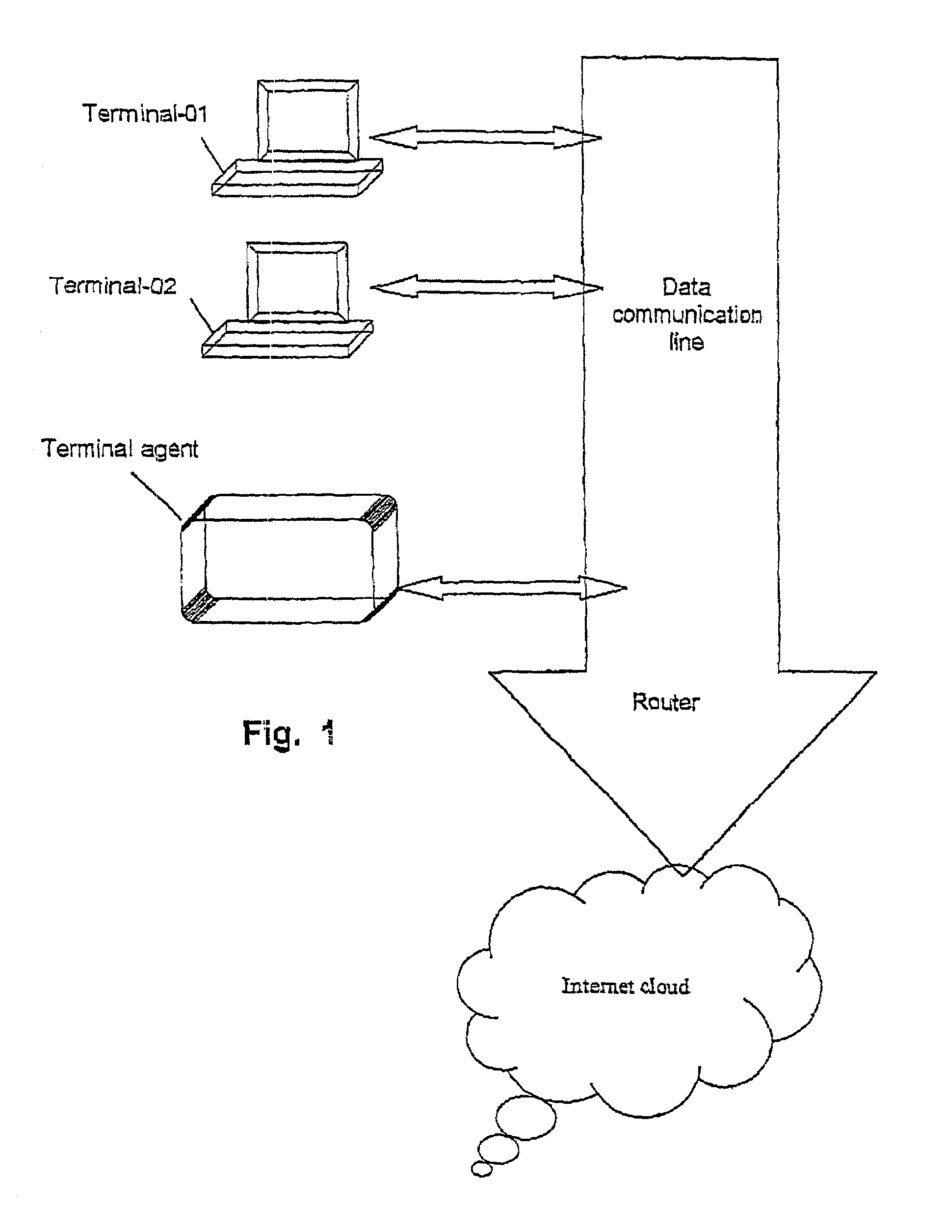
[0026]Referring to FIG. 1, let us assume that terminals 01, 02 . . . are connected to the same communication line, where the communication line is used as internal network (“Intranet”), or external network such as the Internet. According to the present invention it is proposed to connect a designated network probe (hereinafter called “the Terminal Agent”) to the data is communication line. Alternatively, the terminals 01, 02 etc., and the terminal agent may be connected to different data communication lines, or located at different local networks.

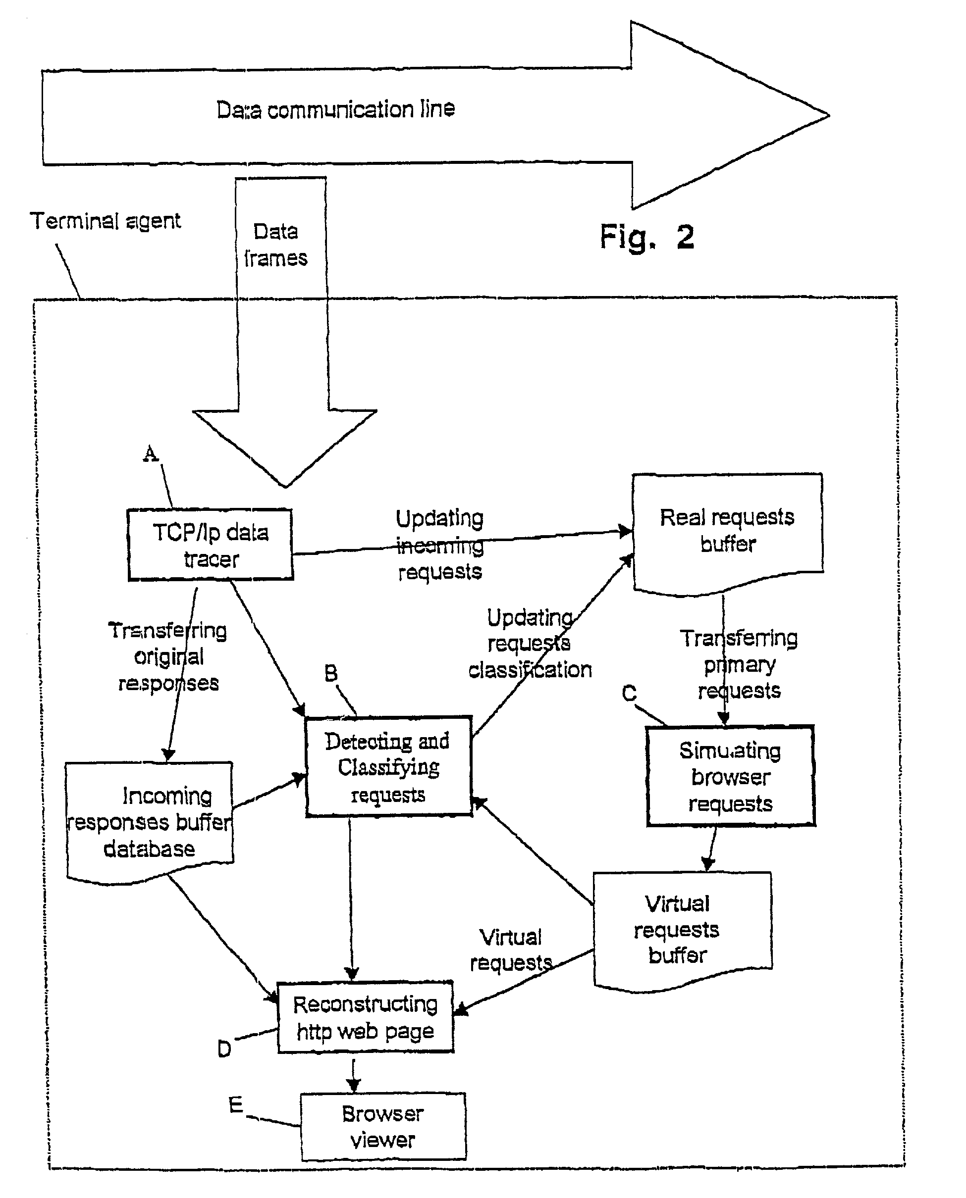
[0027]The general scheme of the terminal Agent operation is illustrated in FIG. 2.

[0028]The Terminal Agent is exposed to all data frames passing through the communication line. The data frames may contain information transferred between the terminals or external data transmission to external sources such as internet servers.

[0029]Let us further assume that the “Owner” of the data communication line, such as ISP or network of a private organ...


PUM


Abstract

A network probe terminal for surveillance of a network communication line and simulating browser activity of a given terminal is disclosed. The probe terminal monitors TCP/IP data packets routed through the communication line and filters relevant requests and responses relating to a given IP address. These requests and responses are analyzed and sorted according to their type and content. Based on the analysis, the probe terminal identifies all relevant data transactions relating to the navigation process of a given terminal. The probe terminal activates a virtual browser simulating the processing of identified data transactions to create navigation presentations similar to the navigation presentations as seen by the user of a given terminal.

Description

[0001]This application is a Continuation of International Patent Application No. PCT / IL01 / 00471 with an international filing date of 23 May 2001, the entire contents of the application which is hereby incorporated in its entirety.BACKGROUND OF THE INVENTION[0002]The present invention is directed to a method and system for enabling surveillance and monitoring of networks communications by analysis of data traversing therethrough.[0003]A huge amount of traffic is flowing through today's computer networks, not all of which is benign. Thus, an owner or supervisor of a given network may be most interested lo be able to track or “listen in” in real time in order to effectively monitor an / or secure the network. Such monitoring or surveillance can be achieved by connecting a probe to the network in order to monitor data traveling between two of more nodes (e.g., user workstations) on the network.[0004]In a system where communication between two nodes is in a form of discrete packets, the ne...

Claims


Application Information

Patent Timeline
IPC IPC(8): G06F15/173G06F15/16H04L12/24H04L12/26H04L12/28H04L29/06H04L29/08
CPCH04L12/2602H04L43/00H04L67/36H04L67/22H04L67/02H04L43/12H04L67/535H04L67/75
Inventor AMIT, NOAHAMIT, YONIEADAN, ZVI
Owner CREDIT SUISSE AS ADMINISTATIVE AGENT
Why Eureka
Try Eureka