Remote debugging

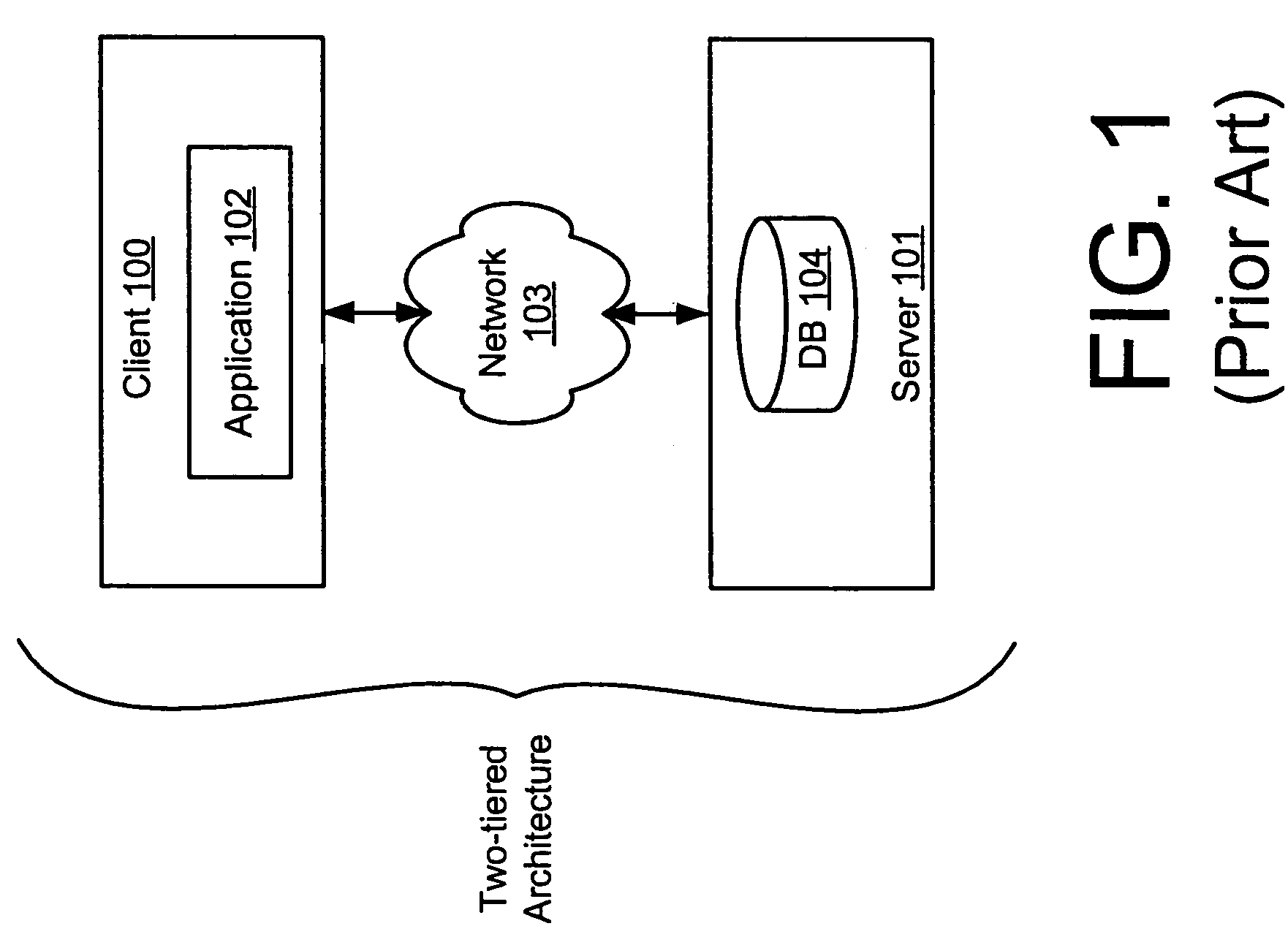
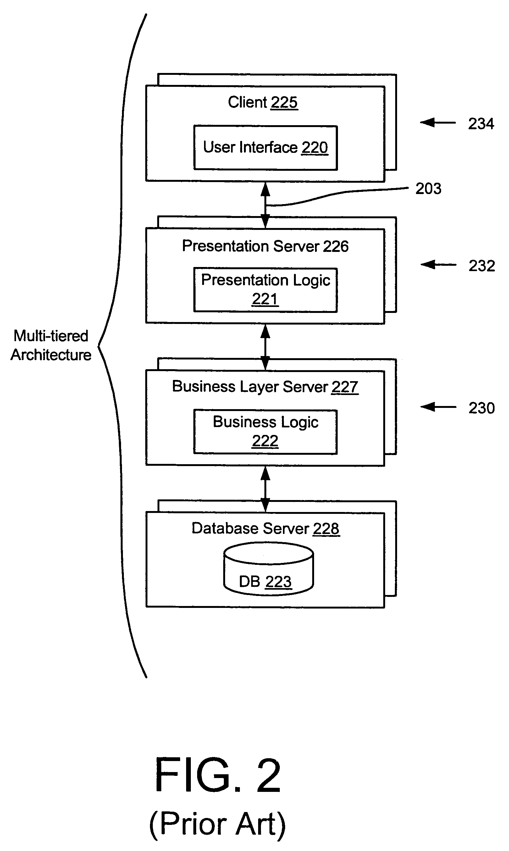
a data processing system and remote debugging technology, applied in the field of remote debugging data processing systems, can solve the problems of a large number of different clients, the limitations of the two-tiered architecture, and the inability to install and maintain up-to-date client-side applications,

Active Publication Date: 2007-05-08
SAP AG
View PDF11 Cites 28 Cited by
  • Summary
  • Abstract
  • Description
  • Claims
  • Application Information

AI Technical Summary

Benefits of technology

[0009]A system and method are described for remotely debugging an application server. In one embodiment, a plurality application servers are organized into groups referred to as “instances.” Each instance may include a group of redundant application servers, one or more debug nodes, and a dispatcher. The dispatcher distributes service requests to each of the application servers in accordance with a load-balancing mechanism. In addition, a central message passing architecture is defined which allows the various instances to communicate with one another. In one embodiment, a debug node is isolated from the load-balancing mechanism. The debug node may also be isolated from the central message passing architecture. A remote node may then debug an application on the debug node, without disrupting processes executing on other application servers in the instance.

Problems solved by technology

The limitations of the two-tiered architecture illustrated in FIG. 1 become apparent when employed within a large enterprise.
For example, installing and maintaining up-to-date client-side applications on a large number of different clients is a difficult task, even with the aid of automated administration tools.
Moreover, a tight coupling of business logic, presentation logic and the user interface logic makes the client-side code very brittle.
Changing the client-side user interface of such applications is extremely hard without breaking the business logic, and vice versa.
This problem is aggravated by the fact that, in a dynamic enterprise environment, the business logic may be changed frequently in response to changing business rules.
Accordingly, the two-tiered architecture is an inefficient solution for enterprise systems.
Although the multi-tiered system illustrated in FIG. 2 provides a more flexible and scalable architecture, it also results in significant additional complexity.

Method used


Image

  • Remote debugging
  • Remote debugging
  • Remote debugging

Examples


Embodiment Construction

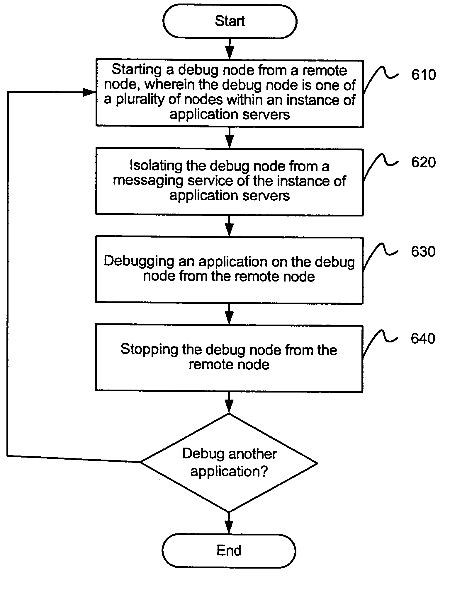
[0018]Embodiments of the invention are generally directed to a system and method for remotely debugging a data processing system. In an embodiment, an instance of application servers includes a debug node. In an embodiment, the debug node is isolated from a load-balancing mechanism used to distribute service requests. The debug node may also be isolated from the central message passing architecture. As is further described below, a remote node may then debug an application on the debug node, without disrupting processes executing on other application servers in the instance.

[0019]A system architecture according to one embodiment of the invention is illustrated in FIG. 3. The architecture includes a central services instance 300 and a plurality of application server instances 310, 320. As used herein, the application server instances, 310 and 320, each include a group of application servers 314, 316, 318 and 324, 326, 328, respectively, and a dispatcher, 312, 322, respectively. The c...


PUM


Abstract

A system and method are described for remotely debugging an application server. In one embodiment, a plurality of application servers are organized into groups referred to as “instances.” Each instance may include a group of redundant application servers, one or more debug nodes, and a dispatcher. The dispatcher distributes service requests to each of the application servers in accordance with a load-balancing mechanism. In addition, a central message passing architecture is defined which allows the various instances to communicate with one another. In one embodiment, a debug node is isolated from the load-balancing mechanism. The debug node may also be isolated from the central message passing architecture. A remote node may then debug an application on the debug node, without disrupting processes executing on other application servers in the instance.

Description

TECHNICAL FIELD[0001]Embodiments of the invention generally relate to the field of data processing systems and, more particularly, to a system and method for remotely debugging data processing systems.BACKGROUND[0002]Traditional client-server systems employ a two-tiered architecture such as that illustrated in FIG. 1. Applications 102 executed on the client side 100 of the two-tiered architecture are comprised of a monolithic set of program code including a graphical user interface component, presentation logic, business logic and a network interface that enables client 100 to communicate over network 103 with one or more servers 101. A database 104 maintained on server 101 provides non-volatile storage for the data accessed and / or processed by application 102.[0003]As is known in the art, the “business logic” component of the application represents the core of the application, for example, the rules governing the underlying business process (or other functionality) provided by the ...

Claims


Application Information

Patent Timeline
Patent Type & Authority Patents(United States)
IPC IPC(8): G06F11/00
CPCG06F11/362
Inventor KILIAN, FRANK
Owner SAP AG
Why Eureka
Try Eureka