Turbojet engine lubrication system

a technology for lubricating systems and turbine engines, which is applied in the direction of turbine/propulsion lubrication, hot gas positive displacement engine plants, gas turbine plants, etc. it can solve the problems of not being suitable for use in all gas turbine systems, heavy and/or bulky, and high construction costs, so as to reduce the viscosity

Inactive Publication Date: 2007-05-15
HAMILTON SUNDSTRAND CORP
View PDF11 Cites 38 Cited by
  • Summary
  • Abstract
  • Description
  • Claims
  • Application Information

AI Technical Summary

Benefits of technology

[0018]Preferably, the tank is in sufficiently close proximity to the engine so as to receive heat rej

Problems solved by technology

While such systems perform quite adequately, they can be heavy and/or bulky, not to mention expensive in construction.
As a consequence, they are not suitable for use in all gas turbine systems.
At the same time, the lubrication system must be capable of operating reliably for the life of the engine and over a wide range of temperatures, typically from minus 40° F. to plus 180° F. Because these engines typically operate at a high rpm, a shaft or gear driven pump system is impractical as well

Method used


Image

  • Turbojet engine lubrication system
  • Turbojet engine lubrication system
  • Turbojet engine lubrication system

Examples


Embodiment Construction

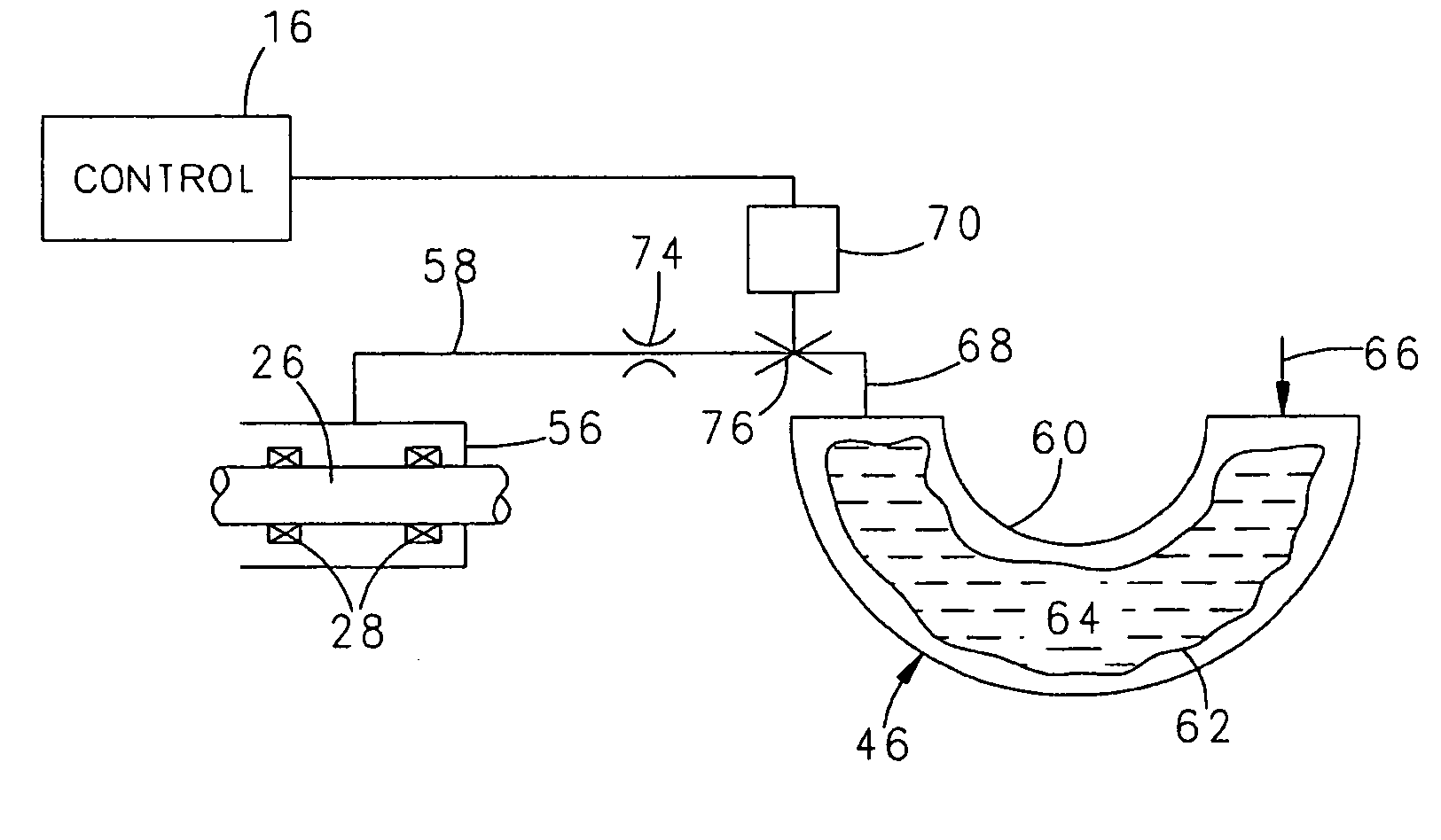
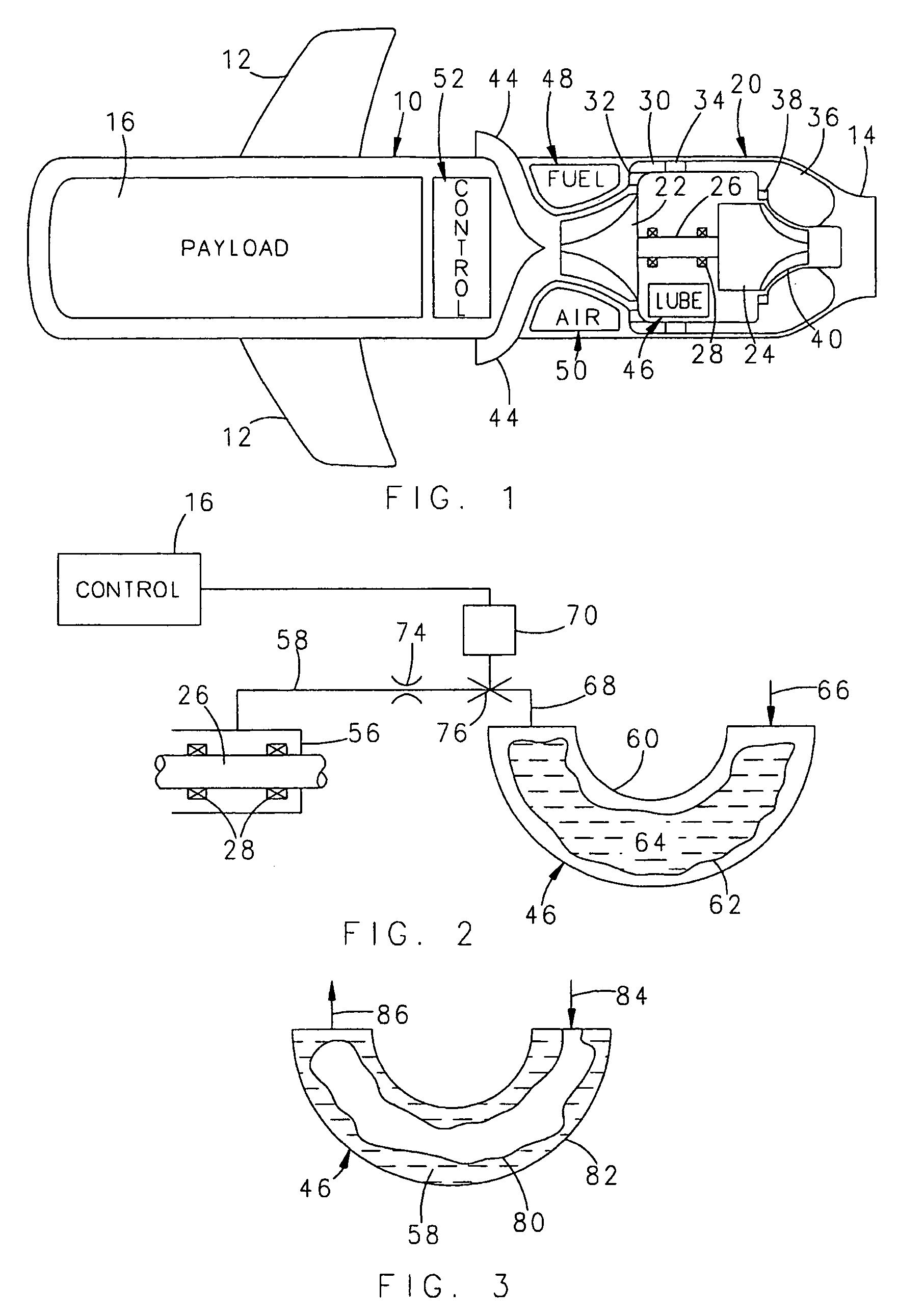
[0027]An exemplary embodiment of the invention is illustrated in the environment of a turbojet driven airborne vehicle of the expendable type, such as a cruise missile or a target drone. The vehicle includes a vehicle body, generally designated 10, which may or may not be provided with wings 12 of conventional construction. At the rear of the body 10 is a jet nozzle 14 by which the body 10 is propelled as a result of hot gases of combustion exiting the nozzle 14.

[0028]In the forward part of the body 10, a payload 16 is located. In the case of a cruise missile, the payload would be munitions whereas in the case of a target drone, the payload 16 might include a parachute or the like to allow recovery and possible re-use of the target drone.

[0029]At the rear of the body 10, a small expendable turbojet engine, generally designated 20, is provided. In the illustrated embodiment, the turbojet engine 20 is of the radial flow type and includes a rotary compressor 22 of conventional construc...


PUM


Abstract

A lubrication system for an expendable gas turbine engine (20) having a rotatable shaft (26) is provided. Bearings (28) journal the shaft (26) for rotation about an axis. The system includes a vessel (46) for containing lubricating oil, a conduit (58) extending from the vessel (46) to the bearings (28), and a solenoid operated valve (70,76) in the conduit (58) and operable to only either fully open or fully closed. A control circuit (16) is provided for pulsing the solenoid (70) at a controlled rate to alternatingly (a) allow oil flow and (b) halt oil flow to the bearings (28) for a time insufficient to cause oil starvation of the bearings (28).

Description

FIELD OF THE INVENTION[0001]This invention relates to lubrication systems for gas turbine engines, and even more particularly, to lubrication systems for expendable turbojet engines.BACKGROUND OF THE INVENTION[0002]Gas turbine engines conventionally include a rotary compressor, a turbine, and a rotary shaft interconnecting the two. As is typical in equipment of all sorts having rotatable components, except when exotic bearings, such as magnetic bearings, are employed, it is necessary to provide for lubrication of the rotary components. In typical gas turbine engines, lubricating oil is provided to bearings journalling the rotary components, recovered and then recycled. These systems require pumps for recovering the lubricating oil as well as for circulating the lubricating oil. While such systems perform quite adequately, they can be heavy and / or bulky, not to mention expensive in construction. As a consequence, they are not suitable for use in all gas turbine systems.[0003]For exam...

Claims


Application Information

Patent Timeline
IPC IPC(8): F02C7/06
CPCF01D25/18
Inventor MCARTHUR, MALCOLM J.JONES, ANTHONY C.
Owner HAMILTON SUNDSTRAND CORP
Why Eureka
Try Eureka