Aft FLADE engine

a flade fan and flade blade technology, applied in the field of flade engines, can solve the problems of difficult to adapt the flade blades of the front fan difficult to adapt the flade blades to the present engine or engine design, and high cost to adapt the existing engine, etc., to achieve reasonable cost, increase the effect of stress and easy demonstration

Active Publication Date: 2007-05-15
GENERAL ELECTRIC CO
View PDF22 Cites 108 Cited by
  • Summary
  • Abstract
  • Description
  • Claims
  • Application Information

AI Technical Summary

Benefits of technology

[0014]The aft FLADE turbine allows a FLADE engine to have a low pressure spool design that is uncompromised because of limitations in rotor speeds and increased stresses caused by the FLADE blade attachment and location. FLADE fan blades mounted on the aft FLADE turbine are not difficult to adapt to present engines or engine designs. The aft FLADE turbine is not very expensive to adapt to an existing engine to test as compared to a front fan mounted FLADE fan. It is also easier to demonstrate some of the system benefits offered by a FLADE engine concept without a great deal of difficulty and at a reasonable cost relative to that of a new low pressure system or defined around an existing core engine.

Problems solved by technology

This can lead to low pressure spool designs that are compromised because of the limitations in rotor speeds and increased stresses caused by the FLADE blade attachment and location.
The front fan mounted FLADE fan blades also are difficult to adapt to present engines or engine designs.
It would be very expensive to adapt an existing engine to test a front fan mounted FLADE fan.
It would be difficult to demonstrate some of the system benefits offered by a FLADE engine concept at a reasonable cost relative to that of a new low pressure system or defined around an existing core engine.

Method used


Image

  • Aft FLADE engine
  • Aft FLADE engine
  • Aft FLADE engine

Examples


Embodiment Construction

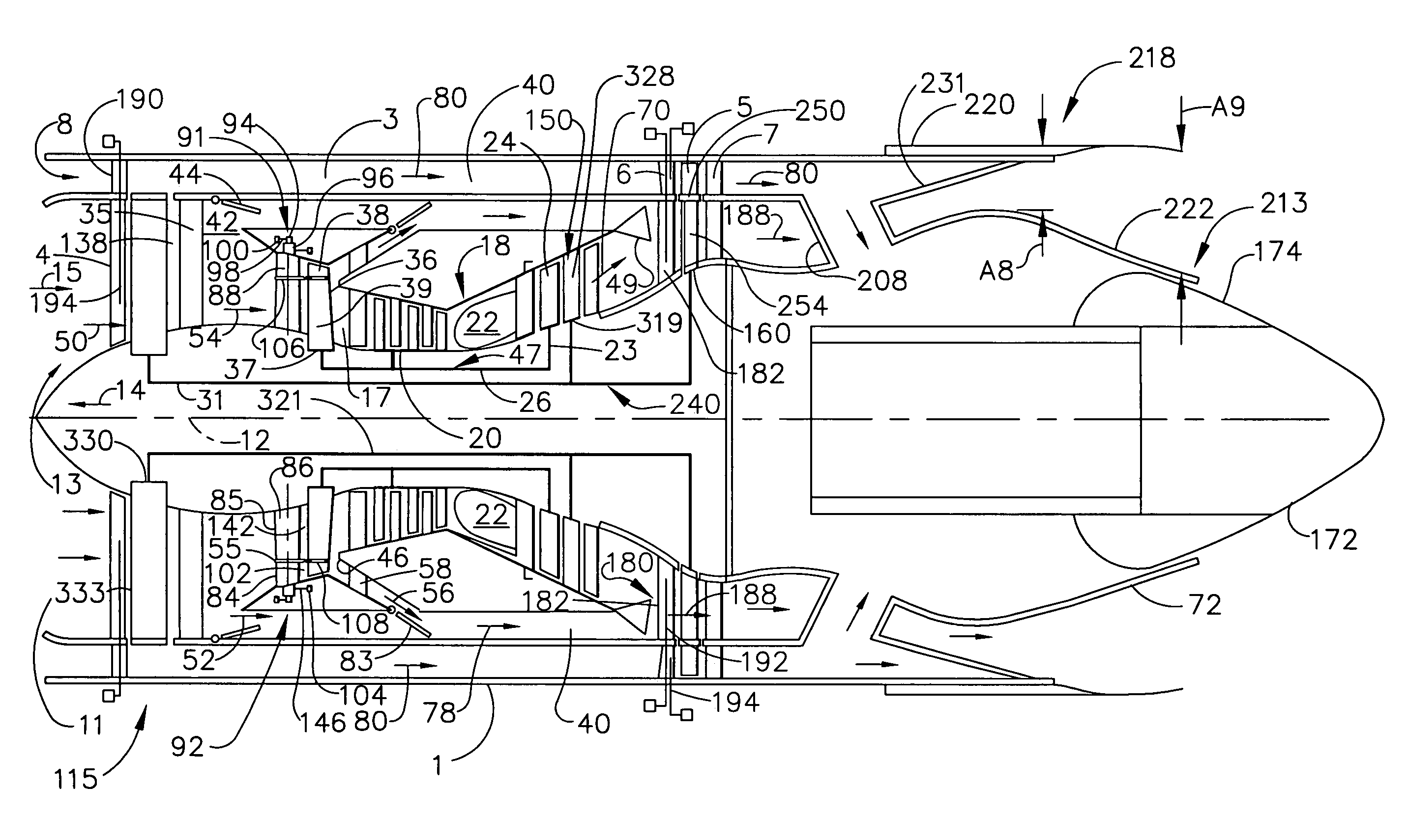
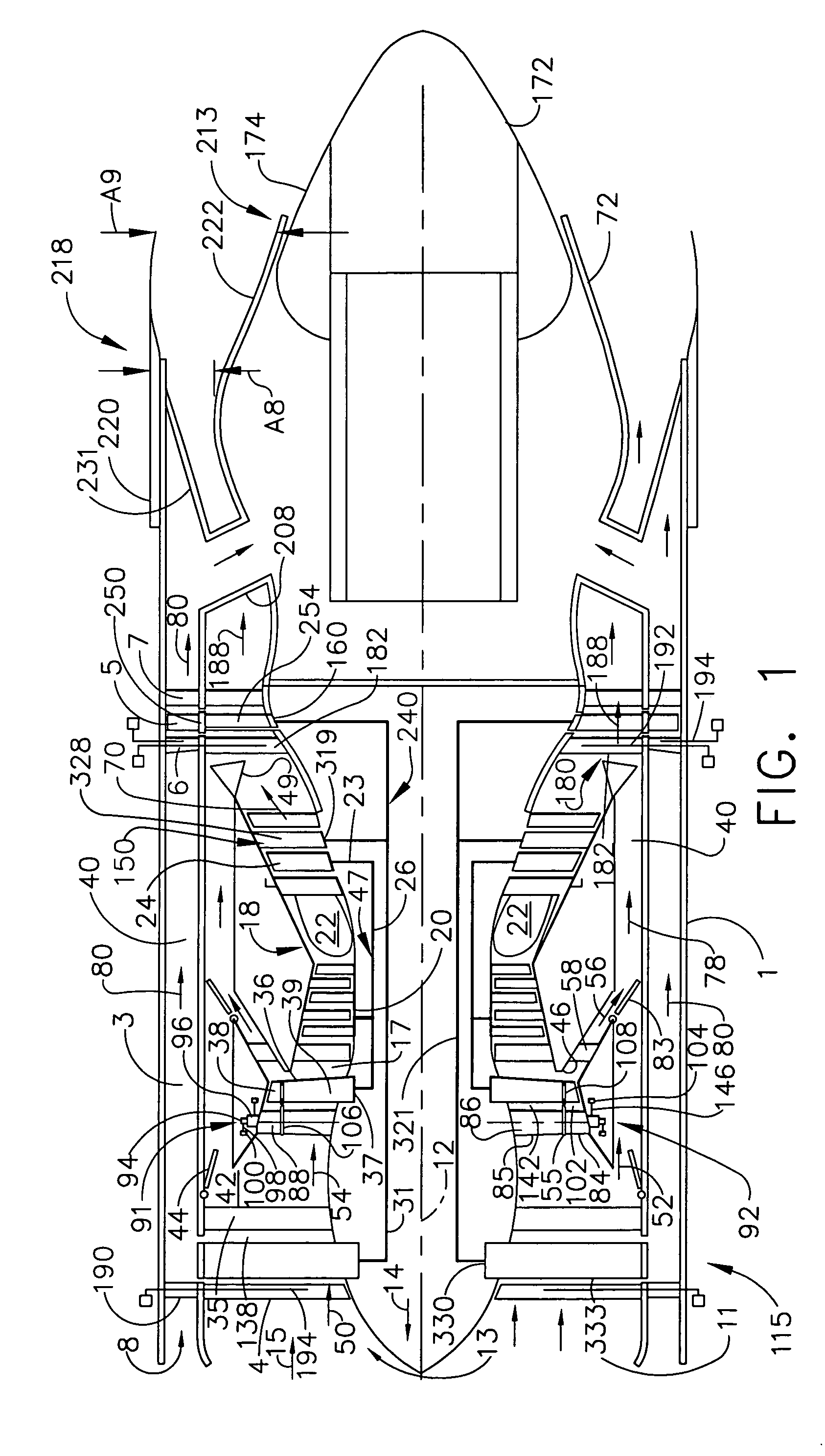
[0027]Schematically illustrated in cross-section in FIG. 1 is an aircraft aft FLADE engine 1 having a fan section 115 with a single direction of rotation fan 330 downstream of variable inlet guide vanes 4. Downstream and axially aft of the fan section 115 is a core engine 18 having an annular core engine inlet17 and a generally axially extending axis or centerline 12 generally extending forward 14 and aft 16. A fan bypass duct 40 located downstream and axially aft of the fan section 115 circumscribes the core engine 18. A FLADE duct 3 circumscribes the fan section 115 and the fan bypass duct 40. Fairings 190 disposed across the FLADE duct 3 surround variable vane shafts 194 passing through the FLADE duct 3 that are used to vary and control the pitch of the variable inlet guide vanes 4.

[0028]The core engine 18 includes, in downstream serial axial flow relationship, a core driven fan 37 having a row of core driven fan blades 36, a high pressure compressor 20, a combustor 22, and a hig...


PUM


Abstract

An aft FLADE gas turbine engine includes a fan section drivenly connected to a low pressure turbine section, a core engine located between the fan section and the low pressure turbine section, a fan bypass duct circumscribing the core engine and in fluid communication with the fan section, and a mixer downstream of the low pressure turbine section and in fluid communication with the fan bypass duct, and an aft FLADE turbine downstream of the mixer. At least one row of aft FLADE fan blades disposed radially outwardly of and connected to the aft FLADE turbine and radially extending across a FLADE duct circumscribing the fan bypass duct. The aft FLADE turbine may be a free turbine or connected to and rotatable with the low pressure turbine section. A power extraction apparatus may be disposed within the engine and drivenly connected to the aft FLADE turbine.

Description

BACKGROUND OF THE INVENTION[0001]1. Field of the Invention[0002]This invention relates to aircraft gas turbine engines and, more particularly, to FLADE engines.[0003]2. Description of Related Art[0004]High performance variable cycle gas turbine engines are being designed because of their unique ability to operate efficiently at various thrust settings and flight speeds both subsonic and supersonic. An important feature of the variable cycle gas turbine engine which contributes to its high performance is its capability of maintaining a substantially constant inlet airflow as its thrust is varied. This feature leads to important performance advantages under less than full power engine settings or maximum thrust conditions, such as during subsonic cruise.[0005]One particular type of variable cycle engine called a FLADE engine (FLADE being an acronym for “fan on blade”) is characterized by an outer fan driven by a radially inner fan and discharging its FLADE air into an outer fan duct w...

Claims


Application Information

Patent Timeline
Patent Type & Authority Patents(United States)
IPC IPC(8): F02K3/02F02K1/38F02K3/077F02K3/062F02K3/065
CPCF02K3/065F02K3/077F02K1/386F05D2250/611F05D2220/327
Inventor JOHNSON, JAMES EDWARD
Owner GENERAL ELECTRIC CO
Why Eureka
Try Eureka