
Adjustable bar for cathedral mount ceiling box

a technology of adjustable bars and ceiling boxes, which is applied in the direction of filing appliances, building repairs, machine supports, etc., can solve the problems of limiting the choice of location for hanging an electrical device, prior art mounting devices exhibiting several limitations for the installation of fans or fixtures on cathedral ceilings, etc., and achieves the effect of greatly simplifying the task of mounting an electrical device to a ceiling, greatly reducing installation time, and easily adjusting

Active Publication Date: 2007-05-15
ARLINGTON INDS
View PDF14 Cites 43 Cited by
  • Summary
  • Abstract
  • Description
  • Claims
  • Application Information

AI Technical Summary

Benefits of technology

[0007]The adjustable mounting assembly of the present invention provides a complete mounting assembly for mounting an electrical device to a cathedral ceiling, including all of the required fastening hardware. All of the installation hardware that is required to complete the task is provided as a part of the mounting assembly.
[0008]An additional advantage is that the required fasteners are held securely in the adjustable mounting assembly in temporary storage receptacles. The temporary storage receptacles provide an advantage in that the fasteners are held securely in the assembly until they are ready to be used. The required fastening hardware is therefore on hand for installation at the time it is required. By freeing up an installer's hands, the task of mounting an electrical device to a ceiling is therefore greatly simplified and the installation time greatly reduced. Additionally, by having all of the required fastening har...

Problems solved by technology

Unfortunately, all of the aforementioned prior art mounting devices require the installation of a separate device, such as a workbox or studs, to support the mounting box.
Additionally, use of the prior art mounting devices limits the choice of location for hanging an electrical device, as the workbox of Corridon's mounting system must be secured to a rafter unless a support structure such as studs are installed between the rafters.
Prior art mounting devices therefore exhibit several limitations in for the installation of fans or fixtures on cathedral ceilings.

Method used


Image

  • Adjustable bar for cathedral mount ceiling box
  • Adjustable bar for cathedral mount ceiling box
  • Adjustable bar for cathedral mount ceiling box

Examples


Embodiment Construction

[0032]The invention is an adjustable mounting assembly for securing an electrical device, such as a fan or a fixture, to a cathedral ceiling.

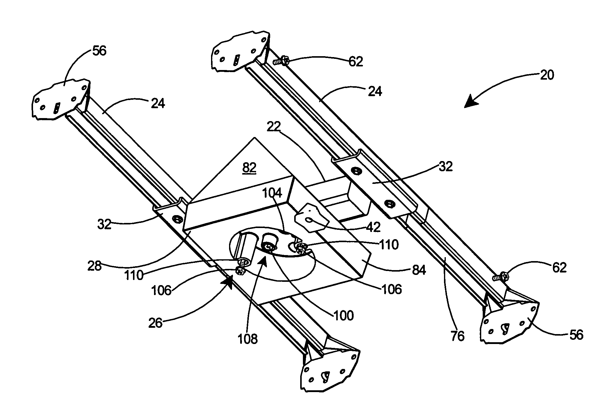
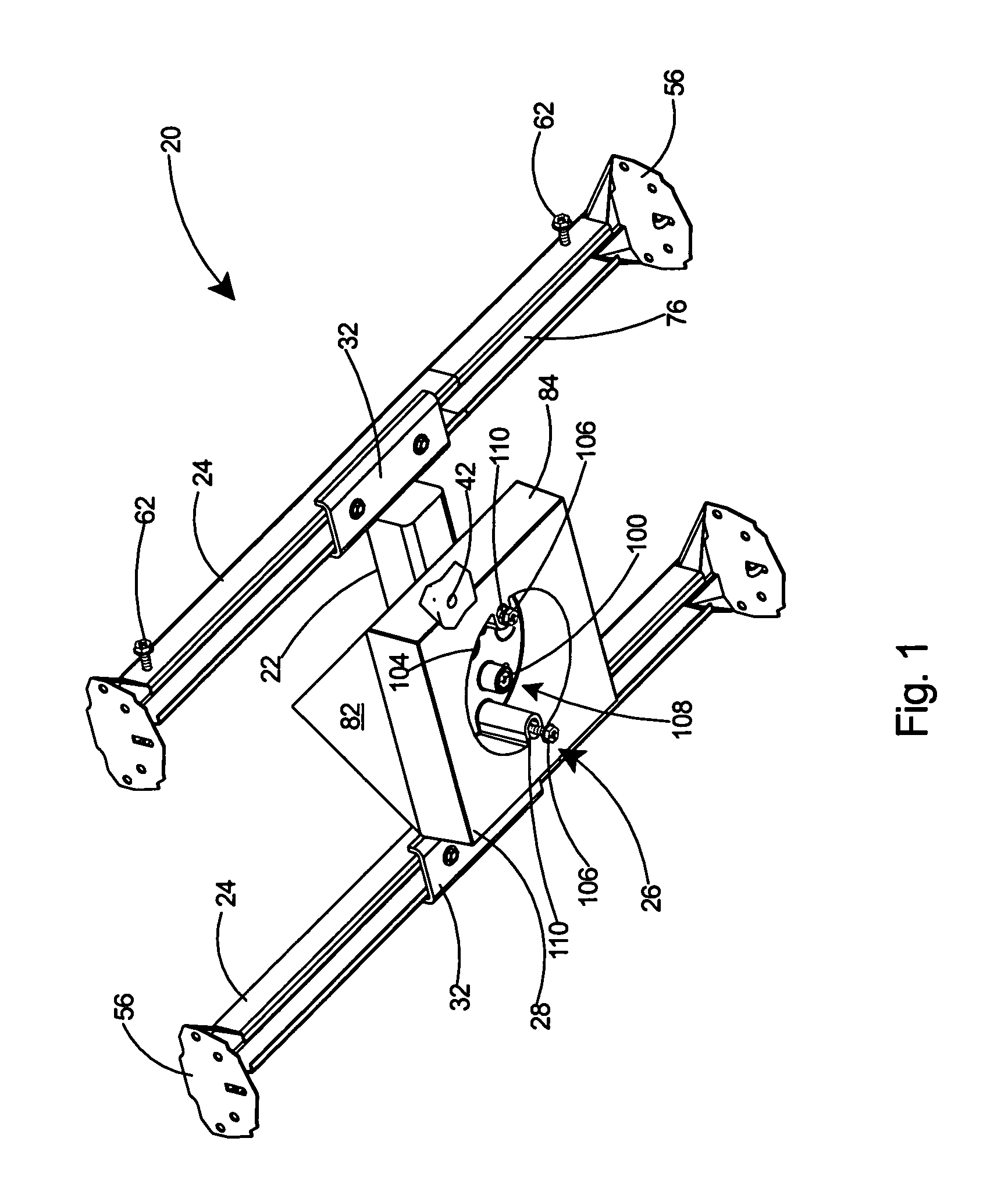
[0033]With reference to FIG. 1, a preferred embodiment is shown of an adjustable mounting assembly 20 including a mounting bracket 22, adjustable mounting bars 24, an electrical box 28, and a securing arrangement 26 for securing an electrical device such as a fan or fixture (not shown) to the adjustable mounting assembly 20.

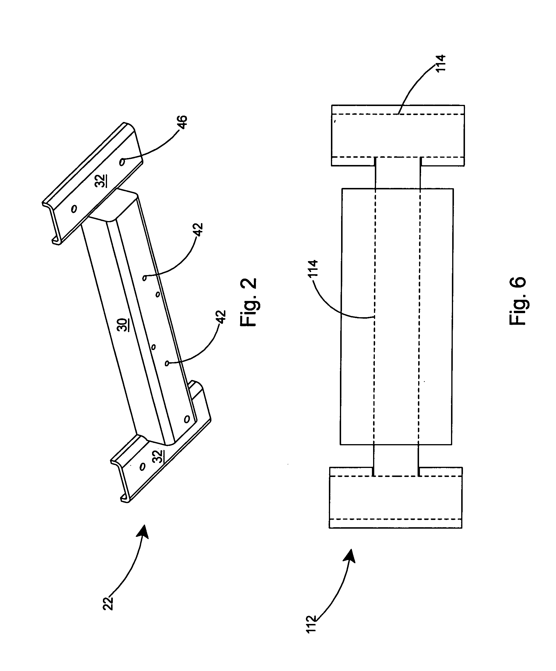
[0034]As shown in FIG. 2, the mounting bracket 22 includes a center bar 30 and two end portions 32.

[0035]Referring to FIG. 5, the center bar 30 of the mounting bracket 22 includes a substantially U-shaped cross section 34. The U-shaped center bar 30 includes a bottom portion 36. The end portions 32 of the mounting bracket 22 are in a first plane 38 and the bottom portion 36 is in a second plane 40. This arrangement, with the bottom portion 36 in a lower plane 40 than the first plane 38 of the end portions 32, will enable eas...


PUM


Abstract

An adjustable mounting assembly for hanging a light fixture, fan, or other electrical device from a cathedral ceiling. The adjustable mounting assembly allows an installer to easily mount an electrical device in any location along the apex of a cathedral ceiling. The adjustable mounting assembly includes a central bracket, adjustable mounting bars, and an arrangement for securing an electrical box to the assembly. All the hardware required for securing the mounting assembly to the rafters and for securing the electrical device thereto is included with the assembly for easily accessibility by the installer.

Description

FIELD OF THE INVENTION[0001]This invention relates to mounting assemblies for electrical boxes and specifically to an adjustable mounting assembly for mounting a fan or light fixture to a cathedral ceiling.BACKGROUND OF THE INVENTION[0002]Builders or homeowners frequently hang electrical devices, such as fans or lighting fixtures, from cathedral ceilings. Typically the electrical devices are hung from the rafters that support the cathedral ceiling.[0003]Several devices have been proposed for installing electrical devices on cathedral ceilings. For example, U.S. Pat. Nos. 5,592,788 and 5,806,269 to Corridon and U.S. Pat. No. 5,503,359 to Patterson propose various devices for mounting electrical devices on cathedral ceilings. Corridon's mounting system includes a cathedral ceiling fixture mount with a central bore. Screws pass through the mounting plate of the electrical device and through the central bore to engage a standard ceiling workbox. Patterson's mounting box is simply a cove...

Claims


Application Information

Patent Timeline
IPC IPC(8): E04G25/00
CPCE04G21/1841Y10S248/906
Inventor GRETZ, THOMAS J.
Owner ARLINGTON INDS
Learn More