Side knock type feeding mechanism

a feeding mechanism and side knock technology, applied in the field of side knock feeding mechanism, can solve the problems of inconvenience of manipulation and unfavorable manipulability, and achieve the effect of enhancing manipulability

Active Publication Date: 2007-05-15
KOTOBUKI PRINTING
View PDF12 Cites 30 Cited by
  • Summary
  • Abstract
  • Description
  • Claims
  • Application Information

AI Technical Summary

Benefits of technology

[0011]When the knock button provided in the side portion of the body is knocked, the rotary member is rotated in the predetermined direction by the knock of the knock button, and the rotary member is rotated in the opposite direction by releasing the knock of the knock button. Since the conversion mechanism converts the rotation into the linear motion of the feeding body by utilizing any rotation of the reciprocating rotations in these rotating directions, the feeding body moves forward in the axial direction inside the body to move the object to be fed forward and feed the object to be fed out of the tip end opening of the body. In this manner, the object to be fed can be fed out by the side knock type manipulation, and therefore manipulability is enhanced.
[0019]According to the present invention, the object to be fed can be fed out by the side knock manipulation, and therefore manipulability can be enhanced.

Problems solved by technology

However, the manipulation to rotate such rotary cylinder requires two hands wherein one hand holds the barrel body at the time of manipulation and the other hand rotates the rotary cylinder, thus causing the problem of inconvenience of the manipulation.
However, even with such knock manipulation, in order to knock the knock body, it is necessary to change the way of holding by hand, and therefore there arises the problem of unfavorable manipulability.

Method used


Image

  • Side knock type feeding mechanism
  • Side knock type feeding mechanism
  • Side knock type feeding mechanism

Examples


Embodiment Construction

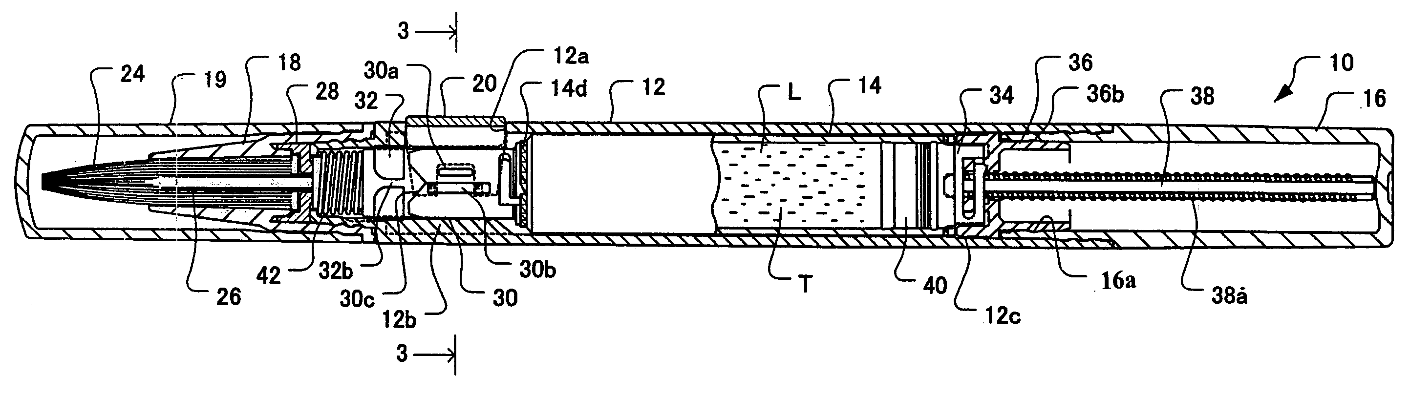
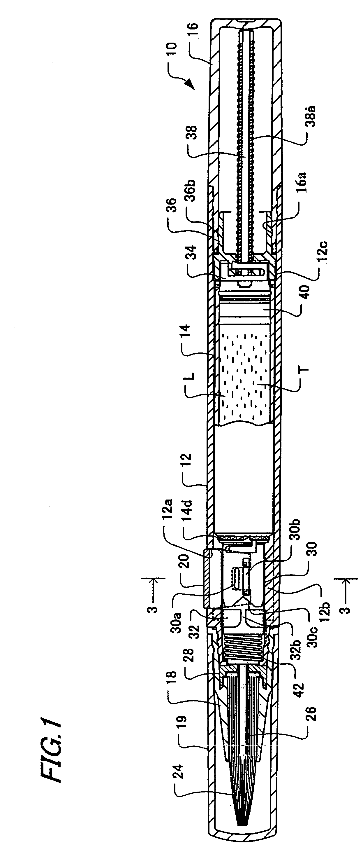
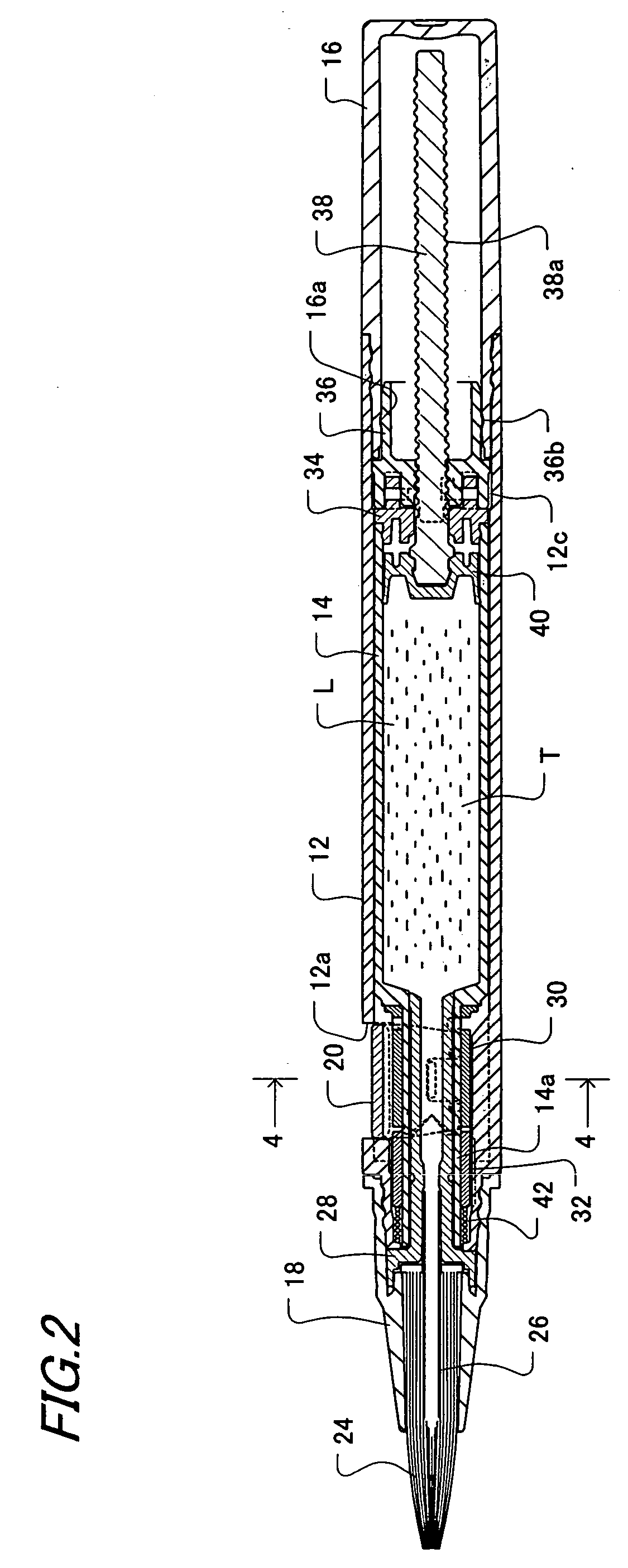
[0031]Hereinafter, an embodiment of the present invention will be explained referring to the drawings. FIG. 1 is an overall longitudinal cross-sectional view showing an embodiment of a liquid container including a side knock type feeding mechanism of the present invention, and FIG. 2 is a longitudinal cross-sectional view of a state in which a cap is removed and side knock manipulation is performed.

[0032]In the drawings, a liquid container 10 including a side knock type feeding mechanism mainly includes a front barrel 12 which an user grips, an inner barrel 14 provided inside the front barrel 12 concentrically with the front barrel 12 and rotatably with respect to the front barrel 12, a rear barrel 16 mounted to a rear end of the front barrel 12, a tip tool 18 mounted to the tip end of the front barrel 12, and a cap 19 detachably fitted on the tip tool 18. An inside of the inner cylinder 14 forms a tank portion T in which a liquid L for correction, writing, cosmetics, etc, is housed...


PUM


Abstract

A side knock type feeding mechanism for feeding an object to be fed inside a body by side knock. A front barrel which houses an object to be fed and is capable of feeding the object to be fed from a tip end opening, a knock button provided on a side portion of the front barrel so as to project and retract with respect to the front barrel, a rotary member which is inside the front barrel, rotates in a predetermined direction by knock of the knock button as a result that the knock button works, and rotates in an opposite direction by releasing the knock, a piston for feeding out the object to be fed, and a conversion mechanism for converting the rotation of the rotary member into a forward travelling motion of the piston in an axial direction inside the front barrel.

Description

BACKGROUND OF THE INVENTION[0001]1. Field of the Invention[0002]The present invention relates to a side knock type feeding mechanism for feeding an object to be fed such as a liquid or solid medium for cosmetics, writing or correction by side knock.[0003]2. Description of the Related Art[0004]Conventionally, as a container for feeding a liquid as an object to be fed, there is the one described in, for example, Japanese Utility Model Publication No. 6-14844. The liquid container described in the above Official Gazette is comprised of a barrel body in which a coating liquid storing portion is formed, a threaded bar projectingly provided at a piston slidably fitted into the storing portion, and a rotary cylinder integrally connecting an inner cylinder member and an outer cylinder member. The outer cylinder member has a ring protruded rib and an engaging claw, which is capable of being resilient in an axial direction in a tip end portion of the outer cylinder member of the rotary cylind...

Claims


Application Information

Patent Timeline
Patent Type & Authority Patents(United States)
IPC IPC(8): A46B11/04B43K5/06A45D34/04B43L19/00A46B11/00B05C17/00B05C17/005B05C17/01B43K8/00B43K8/02B43K8/04B43K24/08B43M11/06
CPCA45D34/04A46B11/0027B43M11/06B43K8/00B43L19/0068B05C17/002A45D34/042A45D2200/055B05C17/0136B05C17/005B43K8/04
Inventor NOGUCHI, YOSHIO
Owner KOTOBUKI PRINTING
Why Eureka
Try Eureka