Cooling system for a seal for turbine vane shrouds

a technology of cooling system and turbine vane, which is applied in the field of turbine vane, can solve problems such as the increase of components' temperatur

Inactive Publication Date: 2007-05-15
SIEMENS ENERGY INC
View PDF16 Cites 63 Cited by
  • Summary
  • Abstract
  • Description
  • Claims
  • Application Information

AI Technical Summary

Benefits of technology

[0005]During operation of a turbine engine, hot combustion gases pass turbine vanes and turbine vane shrouds, which cause these components to increase in temperature. Cooling fluids may be passed through the cooling system in the seal to remove heat from the turbine vane, the turbine vane shroud, and the seal to prevent premature failure of the components. The cooling fluids may be passed through a cooling fluid supply port in the shroud and into a cooling fluid supply orifice in the seal. The cooling fluids may flow through the cooling channel and remove heat from walls of the cooling channel. The cooling fluids may collect in the exhaust channel and be exhausted from the cooling system through a gap between adjacent turbine vane shrouds.
[0007]An advantage of this invention is that the cooling fluids remove heat and reduce the temperature of the surrounding components, thereby substantially reducing the risk of premature failure of the components.
[0008]Another advantage of this invention is that the cooling system improves cooling of the seal groove and reduces hot spot formation in various components of a turbine vane.
[0009]Yet another advantage of this invention is that as cooling fluids are exhausted from the gap between adjacent shrouds, the cooling fluids my reduce the temperature of the external side of the seal from the leading edge to the trailing edge of the seal.

Problems solved by technology

During operation of a turbine engine, hot combustion gases pass turbine vanes and turbine vane shrouds, which cause these components to increase in temperature.

Method used


Image

  • Cooling system for a seal for turbine vane shrouds
  • Cooling system for a seal for turbine vane shrouds
  • Cooling system for a seal for turbine vane shrouds

Examples


Embodiment Construction

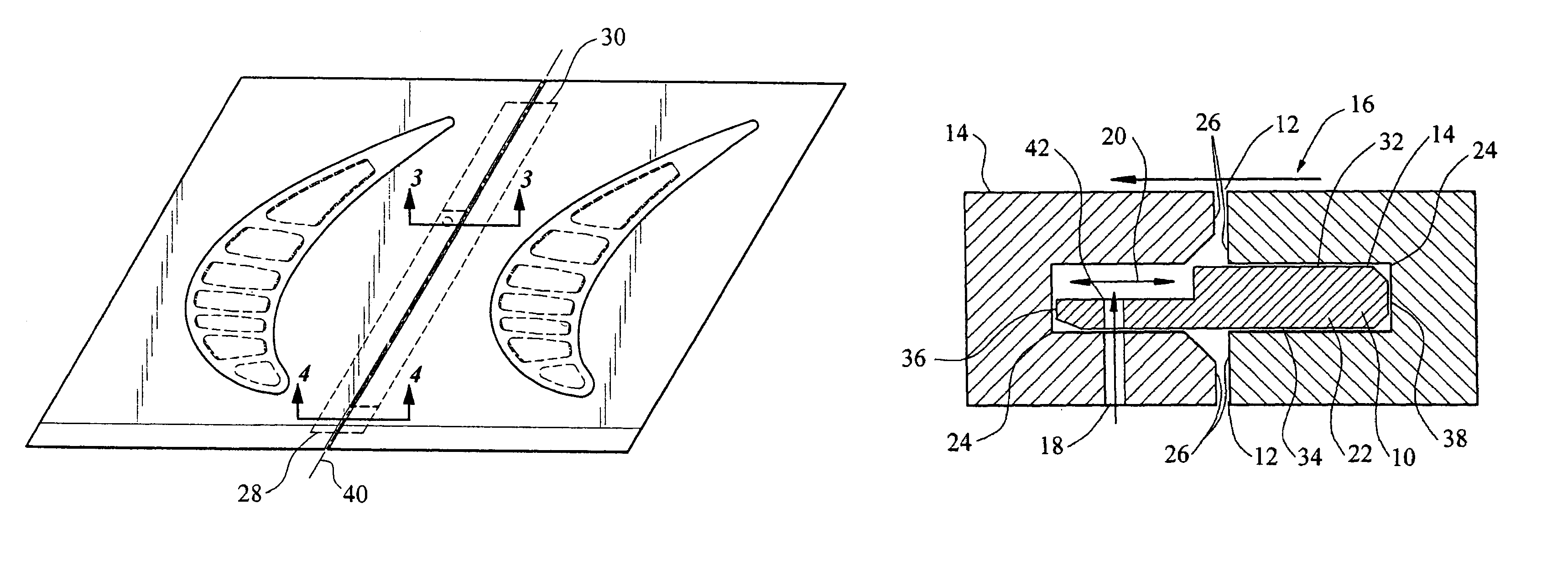
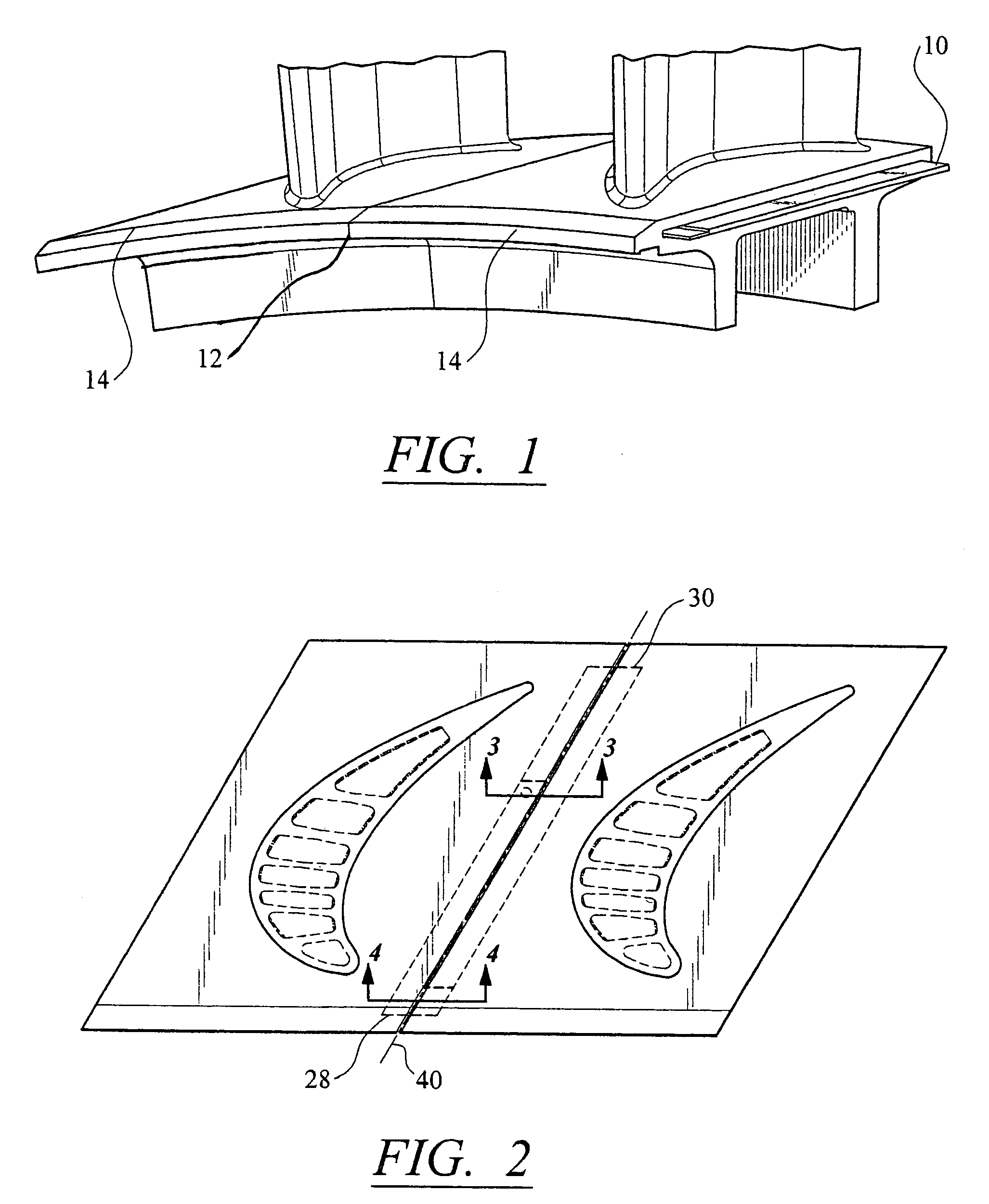
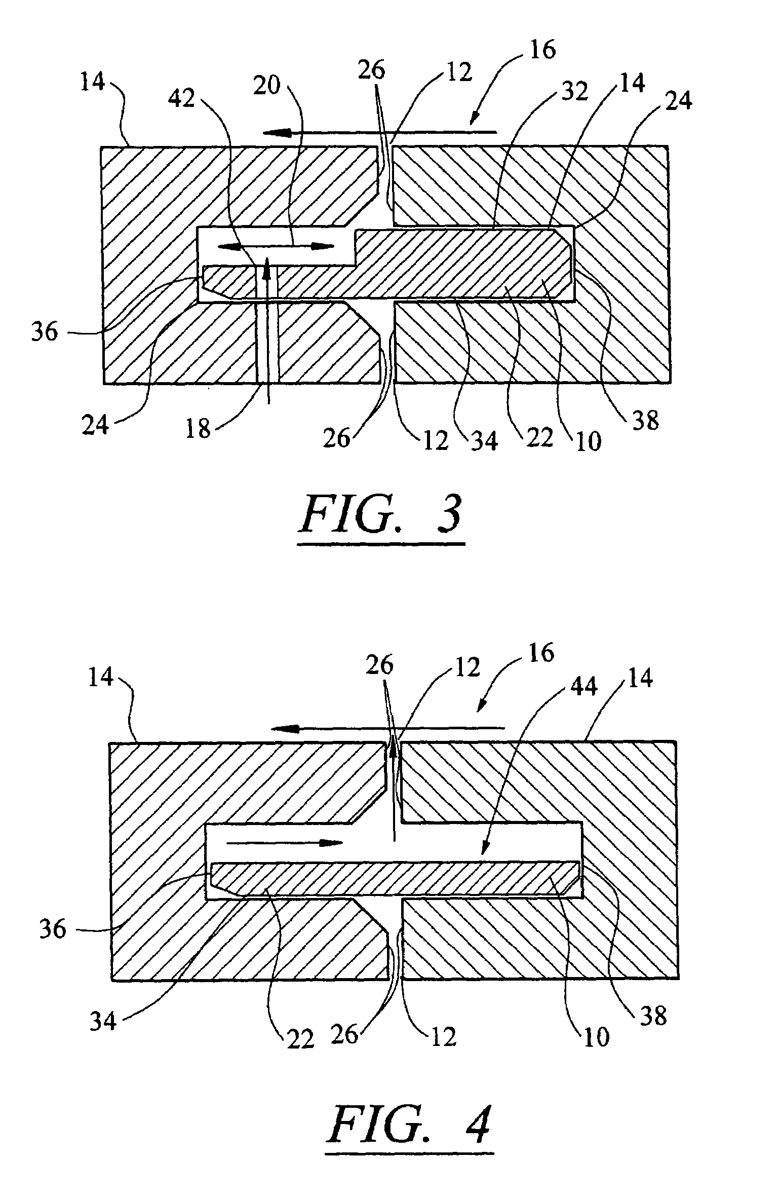
[0016]As shown in FIGS. 1–4, this invention is directed to a seal 10 for sealing gaps 12 between turbine vane shrouds 14, which may also be referred to as shroud segments that collectively form a shroud in a turbine engine. The seal 10 includes a cooling system 16 for removing heat from the seal 10 to prevent premature failure of the seal 10, the turbine vane shroud 14, and the turbine vane. The cooling system 16 may be configured to receive cooling fluids, which may be, but are not limited to, air, from one or more cooling fluid supply ports 18, pass the cooling fluids through the cooling system 16, and exhaust the cooling fluids through a gap 12 between adjacent turbine vane shrouds 14.

[0017]As shown in FIG. 2, the seal 10 may be formed from an elongated body 22 configured to fit into seal grooves 24 on side surfaces 26 of the turbine vane shrouds 14. The seal 10, as shown in FIGS. 2 and 3, may have a first end 28 and a second end 30 generally opposite the first end 28, a top surf...


PUM


Abstract

A seal for sealing a seal groove in a shroud of a turbine vane. The seal may include a cooling system configured to pass cooling fluids through a cooling fluid supply port in a shroud, through a cooling system in which the cooling fluids contact the shroud and the seal, and exhaust the fluids through a gap between adjacent turbine vanes. The seal may include an elongated cooling channel for channeling cooling fluids from a supply to an exhaust channel at a first end. The cooling system may remove heat from the turbine vane shroud, the seal, and other related components, thereby reducing the likelihood of premature failure.

Description

FIELD OF THE INVENTION[0001]This invention is directed generally to turbine vanes and, more particularly, to turbine vane shroud assemblies.BACKGROUND[0002]Typically, gas turbine engines operate at high temperatures that may exceed 2,500 degrees Fahrenheit. During operation, turbine engines expose turbine vanes, turbine vane shrouds, and other components to these high temperatures. As a result, turbine vanes and shrouds must be made of materials capable of withstanding such high temperatures. Turbine vanes often contain cooling systems for prolonging the life of the vanes and reducing the likelihood of failure as a result of excessive temperatures. However, these cooling systems often do not include cooling channels for reducing the temperature of seals positioned in seal grooves between adjacent turbine vanes in turbine shrouds. Without adequate cooling, these seals are susceptible to premature failure. Thus, a need exists for a cooling system for seals in seal grooves of turbine v...

Claims


Application Information

Patent Timeline
Patent Type & Authority Patents(United States)
IPC IPC(8): F01D11/00F01D25/12F01D9/04F01D9/06
CPCF01D11/008F05D2240/57Y10S277/93F01D11/006F01D5/22
Inventor SCHEURLEN, MICHAELGU, XUBIN E.
Owner SIEMENS ENERGY INC
Why Eureka
Try Eureka