When operating solar cells, however, it may happen that individual solar cells are in the shade.
Without the protecting diode, the so-called Zener effect would produce a high
power loss in the shaded
solar cell, leading to a hot spot in this
cell and, thus, almost always to destruction of the same.
Overtemperature and
high field strengths, as could result from
lightning strike, for example, lead to destruction of the diode.
If the diode opens, however, this will initially have no effect on operation, provided the row of cells is producing sufficient power.
If a
cell is shaded, however, the diode can no longer conduct current, a hot spot then arises at the shaded
cell, which may lead to destruction of that cell.
Depending on the local circumstances, this is troublesome and time-consuming, and may even be dangerous, for example, when working on a roof.
Consequently, repair for a large solar installation is usually complex and thus expensive.
As a result, such a failure of a protecting diode often leads to destruction of the cost-intensive solar cells.
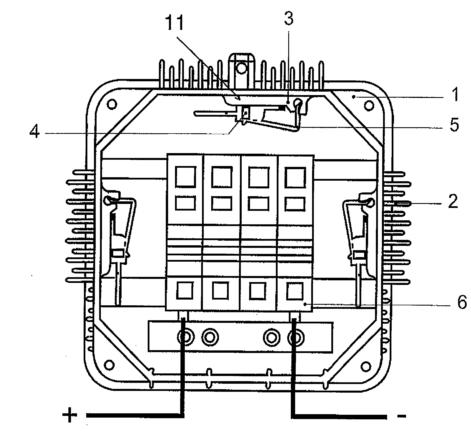
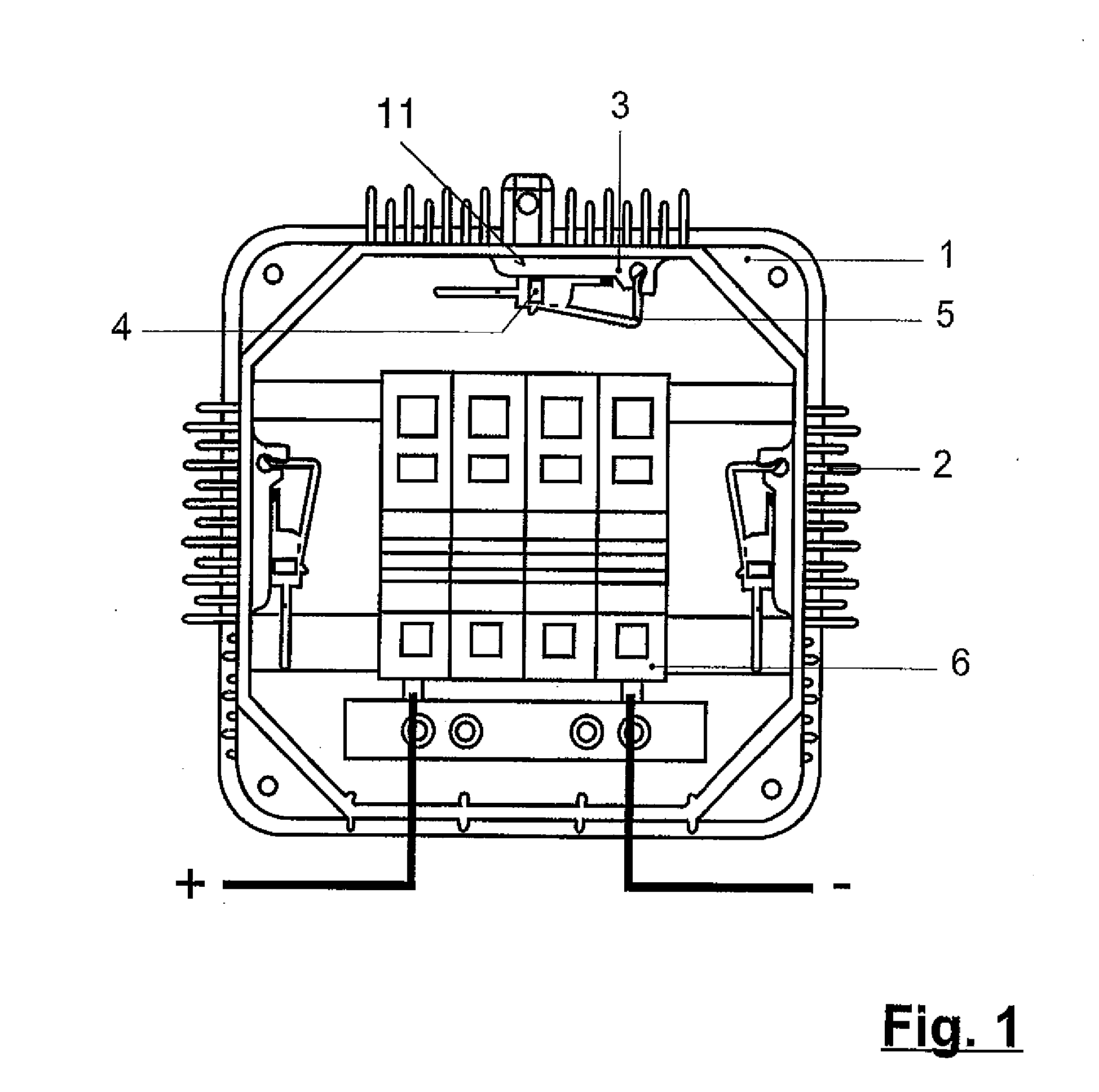
When a
solar cell is shaded, namely, the protecting diodes must
handle high power levels, i.e. they become very hot.
Inadequate of the diodes, or even no cooling at all, can lead to immediate failure in extreme cases; in any case, excessive warming will significantly reduce the service life of the diodes.
Nevertheless, it is still usual to operate the diodes without particular heat dissipation measures, whereby, in practice, exclusively plastic housings are used, which conduct the heat away only poorly.
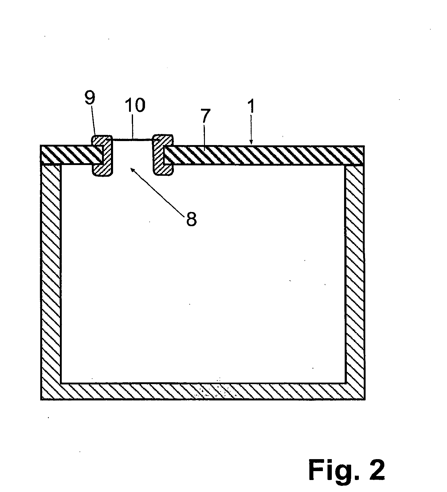
There is no teaching, however, as to how the diodes are to be insulated electrically from the housing.
Because the
cathode or
anode of practically all diodes is always connected with the
metal side of the diode packaging, the described solution would necessarily cause a short-circuit among the protecting diodes.
Furthermore, the proposed screw connection of the diodes will loosen under the influence of temperature fluctuations and the resulting curvature of the
metal side of the diodes, with the result that the
thermal contact between housing and diode is interrupted.
Moreover, the box cannot be opened, repaired or disassembled in case of a defect to components in the box, because it is adhesively sealed and the seal joint filled.
It is also disadvantageous that the module construction is too high, and thus does not fit between the
solar module and the roof in installations as they are mounted nowadays; furthermore, the connector channel is arranged for the axial direction, for which there is similarly no space.
But here, too, the above-described problem, namely, the constant guarantee of a reliable contact between housing and diode, is not solved.

