Bonded body, heat sink-attached insulated circuit board, and heat sink

A technology of heat sink and joint body, applied in the direction of circuit thermal device, circuit, printed circuit, etc., can solve problems such as reduced joint rate and cracking

Active Publication Date: 2021-05-18
MITSUBISHI MATERIALS CORP
View PDF11 Cites 0 Cited by
  • Summary
  • Abstract
  • Description
  • Claims
  • Application Information

AI Technical Summary

Problems solved by technology

[0020] Here, since the above-mentioned intermetallic compound layer is relatively hard and brittle, the intermetallic compound layer may be cracked during a load cooling and heating cycle, and the joining rate may decrease.

Method used


Image

  • Bonded body, heat sink-attached insulated circuit board, and heat sink
  • Bonded body, heat sink-attached insulated circuit board, and heat sink
  • Bonded body, heat sink-attached insulated circuit board, and heat sink

Examples


no. 1 approach

[0047] Hereinafter, embodiments of the present invention will be described with reference to the drawings.

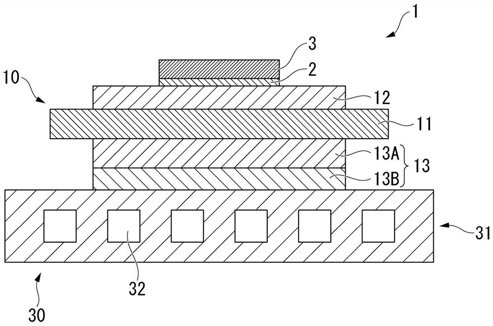
[0048] exist figure 2 , shows the power module 1 using the insulating circuit board with heat sink 30 according to the first embodiment of the present invention.

[0049] The power module 1 includes an insulating circuit substrate 30 with a heat sink and a semiconductor element 3, and the semiconductor element 3 is bonded to one surface of the insulating circuit substrate 30 with a heat sink through a solder layer 2 ( figure 2 middle is above).

[0050] The insulating circuit board with heat sink 30 includes the insulating circuit board 10 and the heat sink 31 bonded to the insulating circuit board 10 .

[0051] The insulating circuit board 10 includes a ceramic substrate 11 constituting an insulating layer, and is arranged on one surface of the ceramic substrate 11 ( figure 2 The circuit layer 12 in the middle is the upper surface) and the metal layer 13 arranged...

no. 2 approach

[0093] Next, a heat sink according to a second embodiment of the present invention will be described. exist Image 6 A heat sink 101 according to the second embodiment of the present invention is shown in .

[0094] The heat sink 101 has a heat sink main body 110 and one side laminated on the heat sink main body 110 ( Image 6 A copper component layer 117 made of copper or a copper alloy. In this embodiment, if Figure 9 As shown, the copper component layer 117 is formed by bonding a copper plate 127 made of a rolled plate of oxygen-free copper.

[0095] A flow path 111 through which a cooling medium flows is provided in the radiator main body 110 . The heat sink body 110 is made of an aluminum alloy having a Si concentration of 1.5% by mass to 12.5% ​​by mass, an Fe concentration of 0.15% by mass or less, and a Cu concentration of 0.05% by mass or less. In addition, Si precipitates are finely dispersed in the heat sink main body 110 (aluminum alloy).

[0096] Here, the ...

Embodiment

[0129] Hereinafter, the results of confirmation experiments conducted to confirm the effects of the present invention will be described.


PUM

PropertyMeasurementUnit
thicknessaaaaaaaaaa
thicknessaaaaaaaaaa
thicknessaaaaaaaaaa

Abstract

Provided is a bonded body in which an aluminum alloy member formed of an aluminum alloy is solid-phase diffusion bonded with a copper member formed of copper or a copper alloy, and which has an excellent thermal cycle reliability, excellent heat dissipation characteristics, and excellent strength. The bonded body includes an aluminum alloy member (31) bonded with a copper member (13B), wherein the aluminum alloy member (31) has an Si concentration in the range of 1.5-12.5 mass%, an Fe concentration of not more than 0.15 mass%, and a Cu concentration of not more than 0.05 mass%. The aluminum alloy member (31) and the copper member (13B) are solid-phase diffusion bonded, and the ratio t2 / t1 is in the range of 1.2-2.0 where t1 is the thickness of a first intermetallic compound layer (41) including a theta phase and disposed on the side of the aluminum alloy member (31), and t2 is the thickness of a second intermetallic compound layer (42) including a non-theta phase other than the theta phase and disposed on the side of the copper member (13B).

Description

technical field [0001] The present invention relates to a joined body formed by joining an aluminum alloy member made of aluminum alloy and a copper member made of copper or copper alloy, and a heat sink is joined to an insulated circuit substrate on which a circuit layer is formed on one side of an insulating layer. An insulating circuit board with a heat sink, and a heat sink in which a copper component layer is formed on a heat sink main body. [0002] This application claims priority based on Patent Application No. 2018-222347 filed in Japan on November 28, 2018, and uses the content here. Background technique [0003] Semiconductor devices such as LEDs and power modules have a structure in which a semiconductor element is bonded to a circuit layer made of a conductive material. [0004] In power semiconductor elements for high-power control used for controlling wind power generation, electric vehicles, hybrid vehicles, etc., since the heat generated is large, insulatin...

Claims


Application Information

Patent Timeline
Patent Type & Authority Applications(China)
IPC IPC(8): B23K20/00C22C21/00H01L23/36H01L23/40
CPCH01L23/36H01L23/3735H01L23/3736C22C21/02B23K20/2333B23K20/026B23K2101/14B23K2101/36B23K2103/10B23K2103/12B23K2103/18B23K20/22C22C21/00H01L23/40B23K2101/40B23K2101/42B23K20/023H05K1/0203H05K3/0061H05K7/20927
Inventor 寺崎伸幸
Owner MITSUBISHI MATERIALS CORP
Why Eureka
Try Eureka