Brush holder assembly for dynamoelectric machines

a technology of dynamoelectric machines and brush holder assemblies, which is applied in the direction of current collectors, supports/encloses/casings, dynamo-electric machines, etc., can solve the problems of brush wear, requiring replacement for maintenance, and affecting the safety of the machine, so as to reduce the overall cost of the brush holder assembly, reduce the number of parts, and improve safety

Active Publication Date: 2007-05-15
GENERAL ELECTRIC CO
View PDF9 Cites 47 Cited by
  • Summary
  • Abstract
  • Description
  • Claims
  • Application Information

AI Technical Summary

Benefits of technology

[0006]The present invention improves safety during the brush retraction process, eliminates all possibility for brushes to be assembled incorrectly and unreliably by providing a mistake proof design, reduces the number of parts, and reduces overall brush holder assembly cost. The present invention provides an improved brush assembly that can be safely released, retracted, and replaced, while maintaining machine operation at synchronous speed and rated load. The present invention simplifies brush box manufacture and cost by eliminating the elongated machined slots in the brush box sides required in prior art design brush assemblies for single brush holders used for the free movement of the holding clip.

Problems solved by technology

Under spring pressure, the brush wears down and requires replacement for maintenance.
However, as the power utility industry has become more safety conscious in recent years, complaints have occurred with respect to the flexibility of the brush handle and worn brush assembly during the brush removal process.
In addition, as new and inexperienced brush holder suppliers have begun supplying parts, it is now apparent that the brush holder assembly shown in FIG. 2 is not “mistake proof”.
The backward installation of clip 3 has lead to a flashover or loss of electrical contact situation between the brush 2 and the slip ring on an operating machine, leading to a forced shutdown of the machine and a rework of the brush holder assembly.

Method used


Image

  • Brush holder assembly for dynamoelectric machines
  • Brush holder assembly for dynamoelectric machines
  • Brush holder assembly for dynamoelectric machines

Examples


Embodiment Construction

[0016]The present invention is directed to a brush holder assembly that, by design, cannot be assembled incorrectly, that includes a reduced number of parts so as to reduce the cost of the design, and that can be safely retracted while a dynamoelectric machine is operating.

[0017]As noted above, FIG. 3A is a cross-sectional view of the brush holder assembly of the present invention showing the hook pin and block arrangement used to hold to the top of a brush the spring exerting a radial pressure on the brush, while FIG. 3B is a partial perspective view of hook pin and block arrangement.

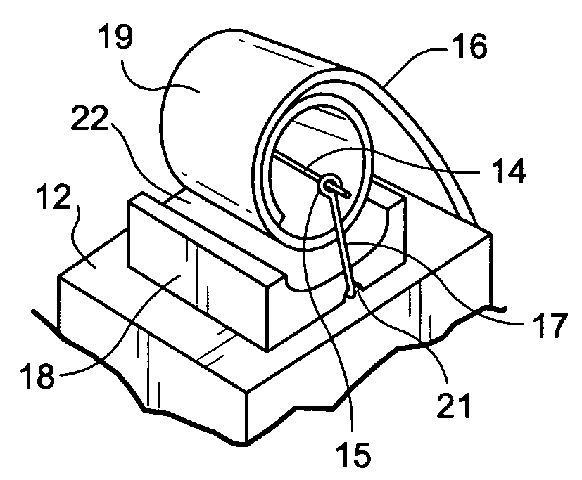
[0018]Referring to FIGS. 3A and 3B, the brush holder assembly 10 of the present invention includes a brush holder 11 and a brush 12 mounted within brush holder 11. In operation, brush 12 transfers current to a rotating contact, such as a slip ring 13, that supplies excitation power to the dynamoelectric machine. Brush 12 is slidable radially inward toward the surface of rotating slip ring 13, and is ma...


PUM


Abstract

A brush holder assembly that cannot be assembled incorrectly includes a brush inserted into a brush holder, a block attached to the top of the brush, a spring engaging the block that applies radial pressure to the block and brush, and a hook pin that holds the spring onto the block. The block includes a semicircular indentation that cradles a coiled portion of the spring and includes a slotted hole for receiving a portion of the hook pin as the block is glued to the top of the brush. The hook pin is a loop terminating at a first end that is a straight pin and terminating at a second end that is a hook-shaped loop in which the straight pin end is inserted. Alternatively, a U-shaped spool assembly can be used to engage the coiled portion of the spring to lock it in the indentation in the block.

Description

BACKGROUND OF THE INVENTION[0001]The present invention relates to dynamoelectric machines, and in particular, to an improved brush holder assembly that cannot be assembled incorrectly and that can be safely released, retracted, and replaced, while maintaining machine operation.[0002]In dynamoelectric machines, a brush holder assembly transfers current from a stationary brush to a rotating contact, such as a slip ring, which then supplies excitation power to a dynamoelectric machine. The brush is mounted in a brush box, and is slidable radially inward toward the surface of the rotating contact. The brush is maintained on the rotating surface of the slip ring by means of a constant pressure spring mounted on a brush holder. Under spring pressure, the brush wears down and requires replacement for maintenance. Power industry expectation developed over the last 20 years is that worn bush assemblies must be able to be removed while a machine is running and under voltage.[0003]Brush holder...

Claims


Application Information

Patent Timeline
Patent Type & Authority Patents(United States)
IPC IPC(8): H01R39/42
CPCH01R39/381H02K5/148H02K13/04
Inventor ANNIS, JOAN IONEVANSCHAICK, THOMAS EDWINRIGOSU, ANTHONY
Owner GENERAL ELECTRIC CO
Why Eureka
Try Eureka