Plasma display panel

a technology of display panel and plasma, which is applied in the manufacture of electrode systems, electric discharge tubes/lamps, instruments, etc., can solve the problems of deterioration of quality, delay of discharge time, and failure of illumination

Inactive Publication Date: 2007-05-15
PANASONIC CORP
View PDF15 Cites 7 Cited by
  • Summary
  • Abstract
  • Description
  • Claims
  • Application Information

AI Technical Summary

Benefits of technology

[0007]This plasma display panel performs stable discharge characteristics, such as a driving voltage, thereby displaying an image stably.

Problems solved by technology

This discharge may delay from the rising of the pulse by a period of time, “a discharge delay time”.
As a result, an electric charge may not be stored in a discharge cell to illuminate actually, thereby causing illumination failure and having quality deteriorate.

Method used


Image

  • Plasma display panel
  • Plasma display panel
  • Plasma display panel

Examples


Embodiment Construction

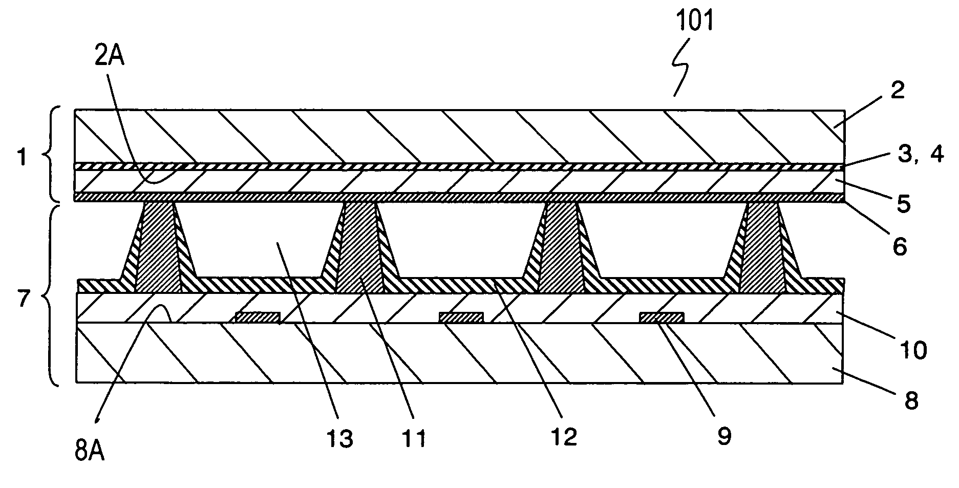
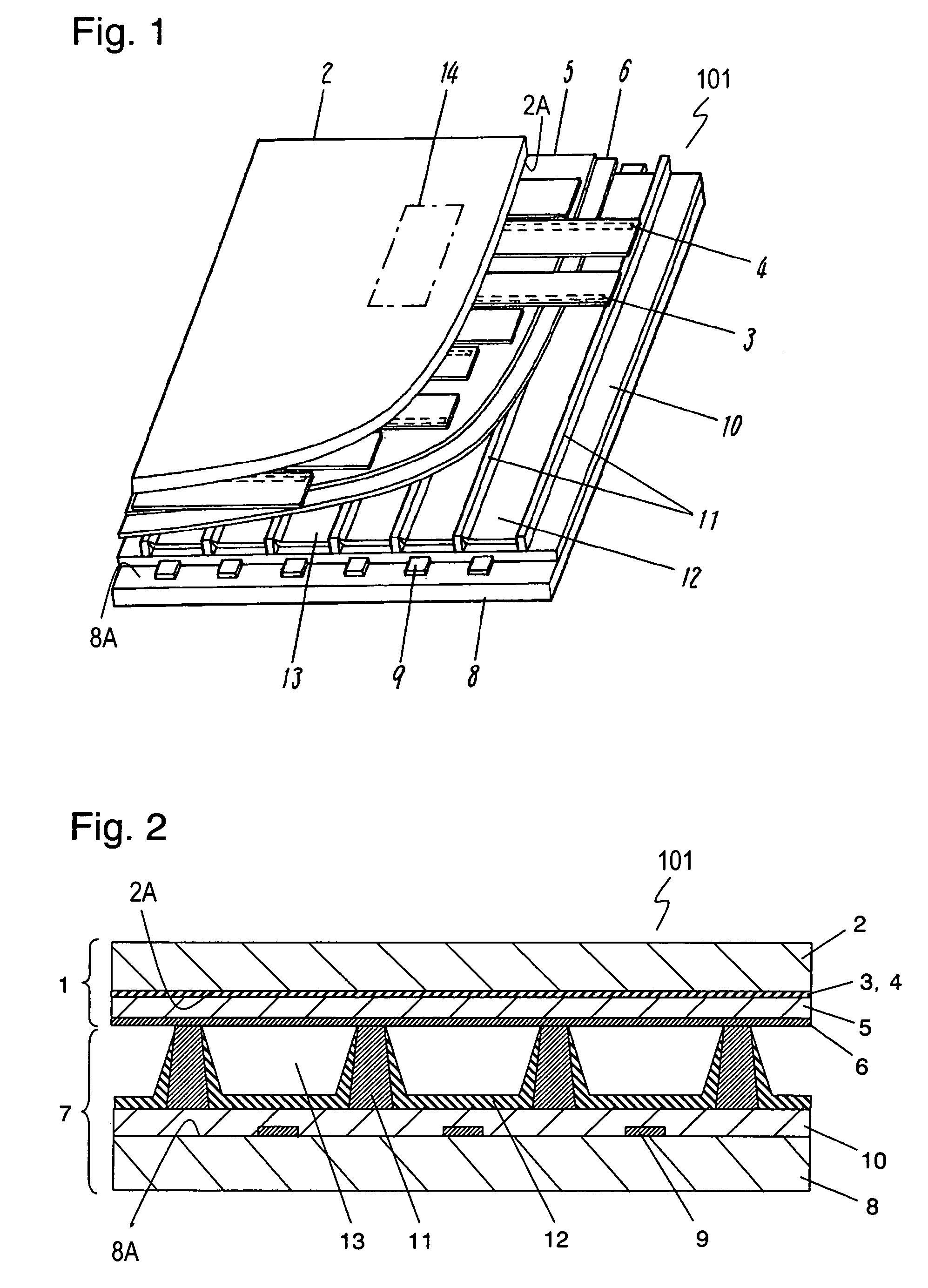
[0013]FIG. 1 is a partially-sectional, perspective view of an AC surface-discharge type plasma display panel (PDP) 101 for schematically illustrating a structure of the PDP. FIG. 2 is a sectional view of PDP 101.

[0014]In front panel 1, a pair of stripe scan electrode 3 and stripe sustain electrode 4 forms a display electrode. Plural pairs of scan electrode 3 and sustain electrode 4, i.e. plural of display electrodes, are provided on surface 2A of front glass substrate 2. Dielectric layer 5 covers scan electrode 3 and sustain electrode 4 is formed, and protective layer 6 for covering dielectric layer 5 is formed.

[0015]In rear panel 7, stripe address electrode 9 is provided on surface 8A of rear glass substrate 8 perpendicularly to scan electrode 3 and sustain electrode 4. Electrode protective layer 10 covering address electrode 9 protects address electrode 9, and reflects visible light in a direction towards front panel 1. Barrier ribs 11 are provided on electrode protective layer 10...


PUM

PropertyMeasurementUnit
pressureaaaaaaaaaa
pressureaaaaaaaaaa
temperatureaaaaaaaaaa

Abstract

A plasma display panel includes a first substrate and a second substrate facing each other to provide a discharge space between the first substrate and the second substrate, a scan electrode and a sustain electrode both provided on the first substrate, a dielectric layer for covering the scan electrode and the sustain electrode, and a protective layer provided on the dielectric layer. The protective layer includes magnesium oxide, magnesium carbide, and silicon. This plasma display panel performs stable discharge characteristics, such as a driving voltage, thereby displaying an image stably.

Description

TECHNICAL FIELD[0001]The present invention relates to a plasma display panel for displaying an image.BACKGROUND OF THE INVENTION[0002]Various types of display devices, such as a cathode ray tube (CRT), a liquid crystal display (LCD), and a plasma display panel (PDP), which are to be used for a high-definition and large display television, have been developed.[0003]The PDP includes phosphor layers for emitting three primary colors, red (R), green (G), and blue (B) so as to perform full color display by adding and mixing three primary colors (red, green, and blue). The PDP has a discharge cell, and generates visible light by exciting phosphor layers with ultraviolet rays generated by a discharge in the discharge cell, thereby displaying an image.[0004]In an AC type PDP, an electrode for main discharge is generally covered with a dielectric layer, and performs memory driving to reduce a driving voltage. When the dielectric layer deteriorates due to an impact of ions generated by the di...

Claims


Application Information

Patent Timeline
Patent Type & Authority Patents(United States)
IPC IPC(8): H01J17/49H01J9/00H01J9/24
CPCH01J9/02H01J11/12H01J11/40H01J9/241G09G3/291
Inventor HASEGAWA, KAZUYUKIMIZOKAMI, KANAMEOE, YOSHINAOAOKI, MASAKIHIBINO, JUNICHI
Owner PANASONIC CORP
Why Eureka
Try Eureka