
Liquid crystal display and method of driving liquid crystal display

Active Publication Date: 2007-05-15
JVC KENWOOD CORP A CORP OF JAPAN
View PDF9 Cites 7 Cited by
  • Summary
  • Abstract
  • Description
  • Claims
  • Application Information

AI Technical Summary

Benefits of technology

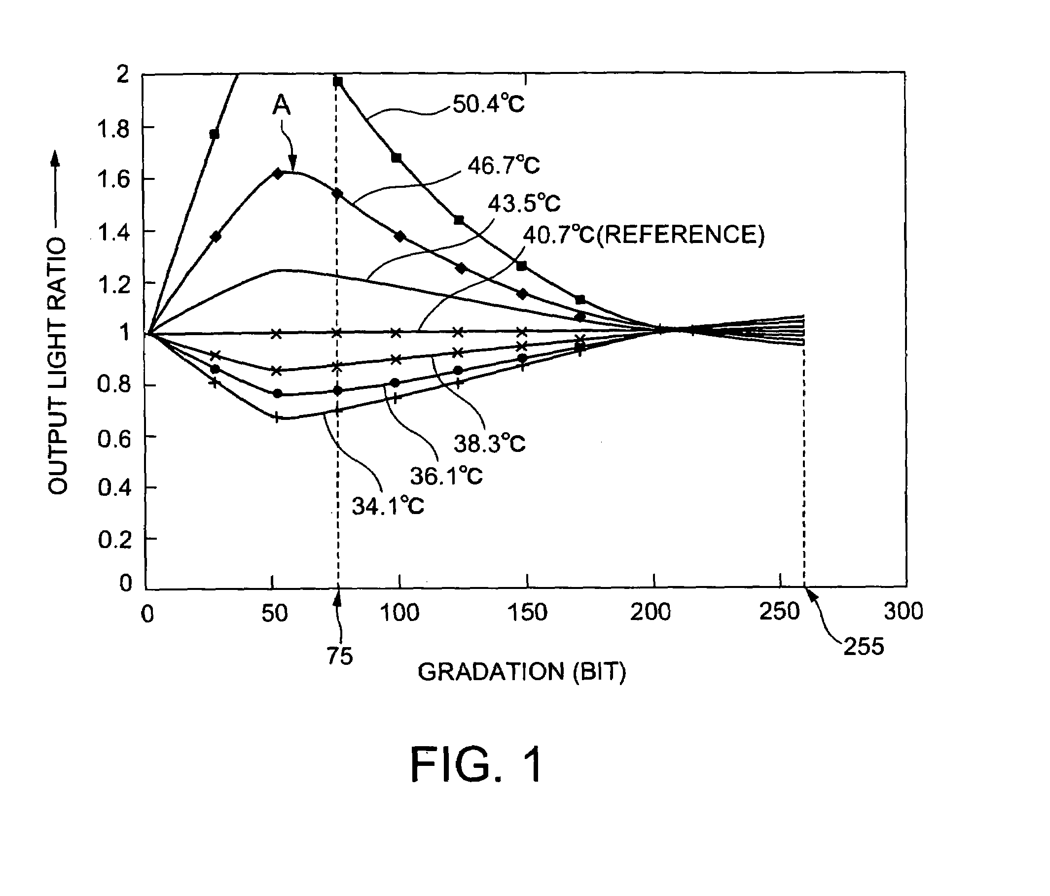
[0016]A purpose of the present invention is to provide a liquid crystal display and a method of driving a liquid crystal display in which the variation in the gamma characteristics of a liquid-crystal display unit can be compensated for against change in temperature.
[0017]Another purpose of the present invention is to provide a liquid crystal display and a method of a liquid crystal display that provide images of stable quality by controlling the temperature of a liquid-crystal display unit.

Problems solved by technology

Nevertheless, this type of display is prone to generation of noises on the video signals and effects of pseudo video signals, with D. C. components being easily applied to the liquid crystal to cause residual images, thus shorting the life of a display panel.
The variation in the gamma characteristics cannot be compensated for, only, by increasing or decreasing the output, because it is a non-linear variation, hence no feasible compensation techniques being proposed.

Method used


Image

  • Liquid crystal display and method of driving liquid crystal display
  • Liquid crystal display and method of driving liquid crystal display
  • Liquid crystal display and method of driving liquid crystal display

Examples


first embodiment

[0043

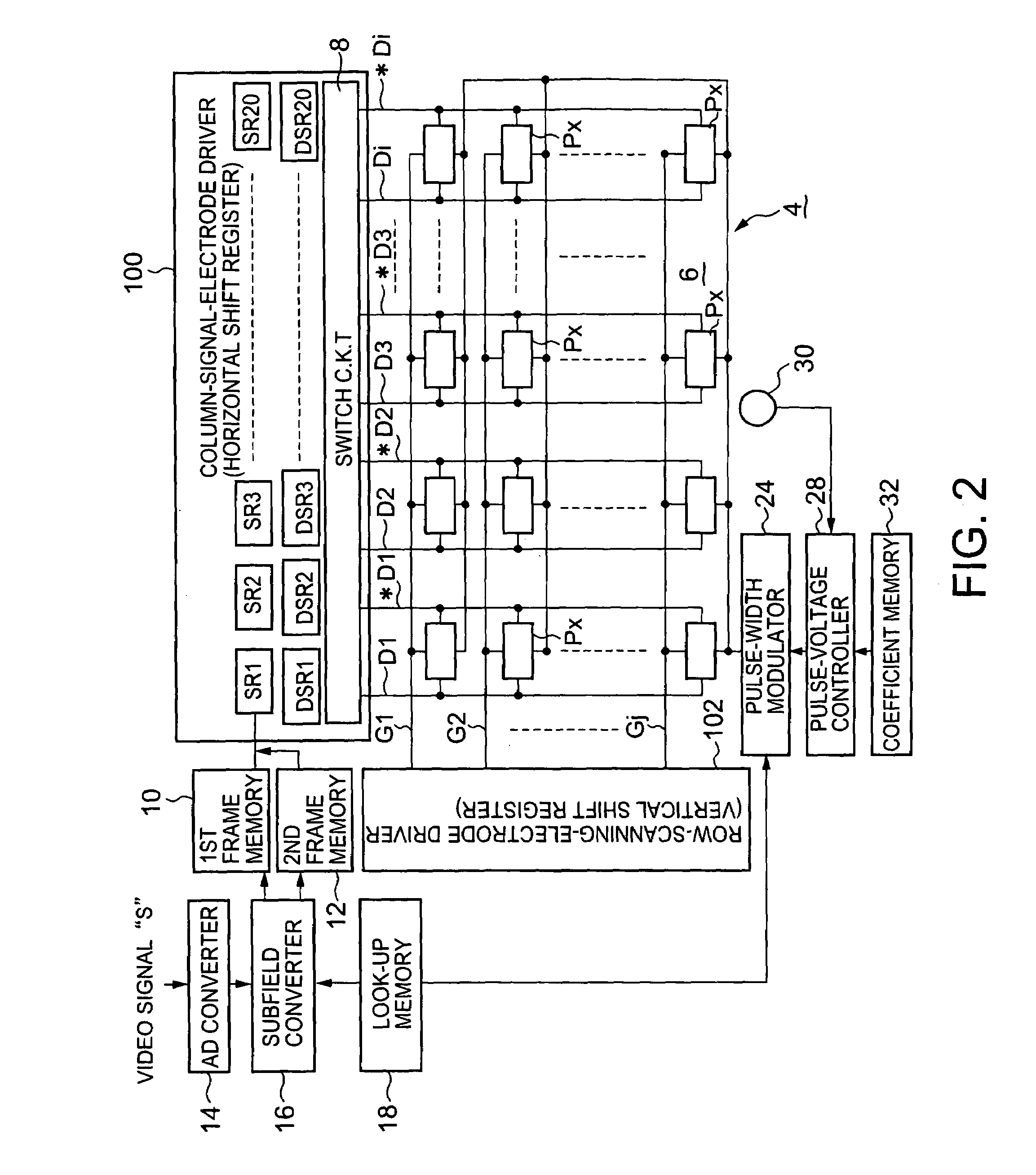
[0044]FIG. 2 shows a block diagram of a first embodiment of an active-matrix display according to the present invention.

[0045]In FIG. 2, first column-signal electrodes D1, D2, D3, . . . , and Di are aligned on an active-matrix substrate 6. Also aligned on the substrate 6 are row-scanning electrodes G1, G2, G3, . . . , and Gj, intersecting with the column-signal electrodes. Provided along the first column-signal electrodes are second column-signal electrodes *D1, *D2, *D3, . . . , and *Di for supplying inverted signals of those supplied through the first column-signal electrodes.

[0046]A pixel Px is provided at the intersection of each column-signal electrode D (D1, D2, D3, . . . , and Di) and each row-scanning electrode G (G1, G2, G3, . . . , and Gj).

[0047]These pixels and column- and row-signal electrodes constitute a liquid-crystal display unit 4.

[0048]A column-signal-electrode driver 100 is equipped with horizontal shift registers SR1, SR2, SR3, . . . , and SR20, and DSR1, DS...

second embodiment

[0105

[0106]FIG. 8 shows a block diagram of a second embodiment of an active-matrix display according to the present invention. The elements shown in FIG. 8 the same as or analogous to those shown in FIG. 2 are given the same reference numerals and not explained.

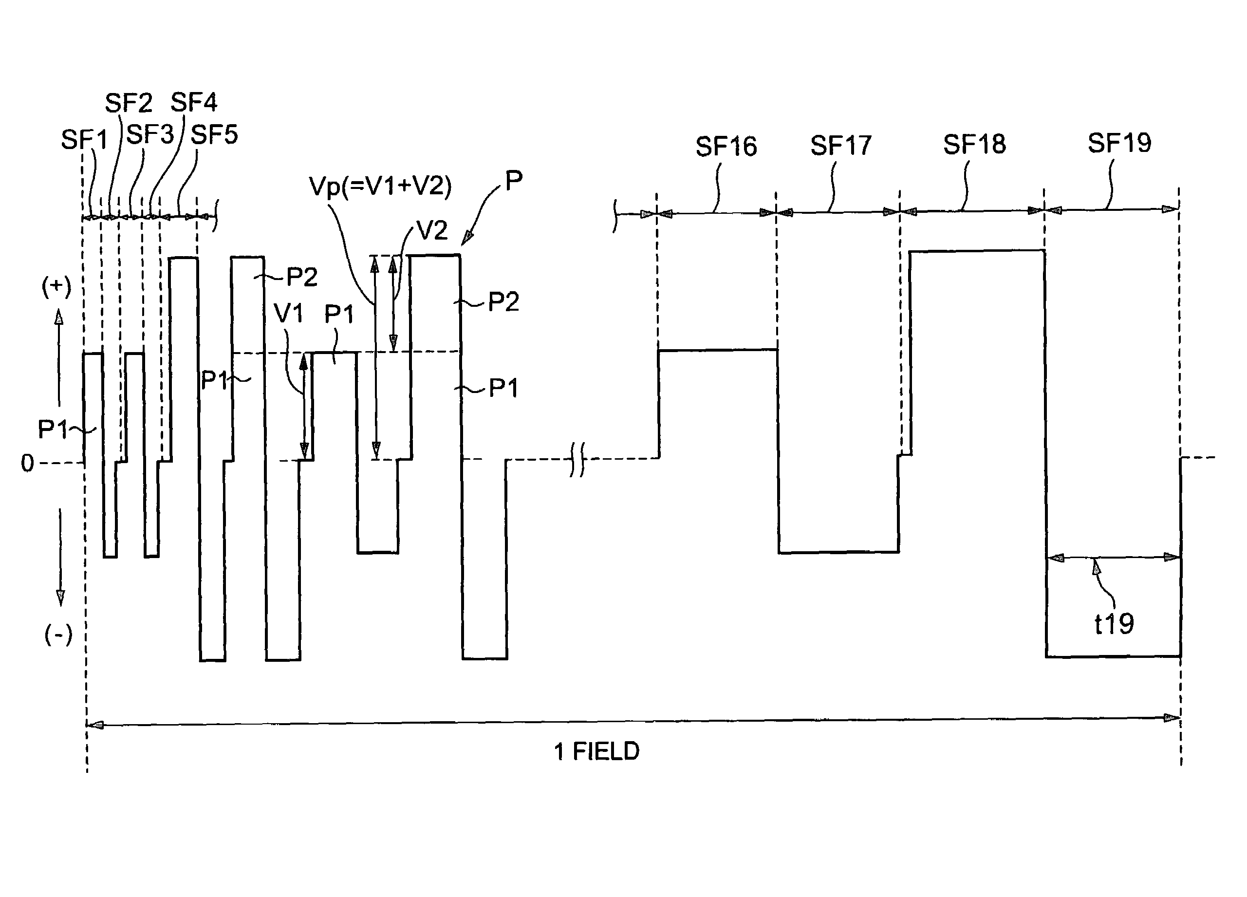
[0107]The second embodiment of the active-matrix display shown in FIG. 8 is equipped with a subfield-period controller 40 connected to the pulse-width modulator 24, for varying the subfield period of one or more of the subfields discussed above, such as shown in FIG. 3, so as to compensate for change in the gamma characteristics of the liquid-crystal display unit 4, due to change in temperature.

[0108]Connected to the subfield-period controller 40 is the temperature sensor 30, such as a thermocouple, for monitoring the temperature of the liquid-crystal display unit 4, the monitored temperature being sent to the controller 40. The thermocouple may be embedded in the active-matrix substrate 6.

[0109]The subfield period controller...

third embodiment

[0140

[0141]FIG. 10 shows a block diagram of a third embodiment of an active-matrix display according to the present invention.

[0142]The third embodiment of the active-matrix display shown in FIG. 10 is mainly equipped with a subfield controller 54 for converting an input video signal into a digital signal and diving one field of the digital signal into a plurality of subfields; a liquid-crystal display unit 56 having multiple pixels arranged in a matrix to display images when the digital signal is supplied; a temperature sensor 57 for monitoring the temperature of the display unit 56; a cooling unit 59 for cooling the display unit 56; and a controller 61 for controlling the cooling unit 59 in accordance with the monitored temperature.

[0143]The subfield controller 54 is equipped with an A / D converter 58 for converting an input video signal into a digital signal; a subfield converter 60 for dividing one field of the digital video signal into 19 subfields; a look-up memory 62 for stori...


PUM


Abstract

A liquid crystal display including a liquid-crystal display unit having a matrix of multiple pixels. A field of a digital input video signal to be supplied to the liquid-crystal display unit is divided into a plurality of subfields. The voltage of the digital video signal is adjusted per subfield to compensate for change in gamma characteristics of the liquid-crystal display unit. Instead of the voltage, the period of at least one subfield of the video signal can be adjusted for compensating for change in the gamma characteristics of the liquid-crystal display unit.

Description

BACKGROUND OF THE INVENTION[0001]The present invention relates to an active-matrix liquid crystal display driven by digital signals.[0002]Active-matrix displays are usually driven by analog signals that control drive voltages for liquid crystals, such as, disclosed in Japanese Unexamined Patent Publication No. 11-174410 (1999).[0003]There are several modes for liquid crystals, such as VA (Vertical Aligned) and MTN (Mixed-Mode Twisted Nematic). Particularly, VA is used for achieving high contrast ratio.[0004]Active-matrix displays have multiple pixels formed with a liquid crystal filled between an active-matrix substrate and another substrate facing the former substrate. A signal supplied to each pixel is stored in a capacitor provided for the pixel, to drive the liquid crystal.[0005]This type of active-matrix display provides enhanced gradation with voltages supplied to the liquid crystal constant for one-field period but varying in accordance with the level of video signals. Nevert...

Claims


Application Information

Patent Timeline
IPC IPC(8): G09G3/36G09G3/20
CPCG09G3/3648G09G3/2022G09G3/3614G09G2300/0842G09G2300/0857G09G2320/0276G09G2320/041
Inventor SHIMIZU, SHIGEO
Owner JVC KENWOOD CORP A CORP OF JAPAN
Learn More