Apparatus and method for testing an impact and/or vibration absorbent material

a technology of applied in the direction of instruments, chairs, transportation and packaging, etc., can solve the problems of spinal system disorders, repeated impact and/or vibration of the human body, and the amount of impact force transferred to an object by the protective glove-covered hand can be significantly increased, and the effect of improving the impact and/or vibration absorption ability of a material

Active Publication Date: 2007-05-22
HONDA MOTOR CO LTD
View PDF45 Cites 10 Cited by
  • Summary
  • Abstract
  • Description
  • Claims
  • Application Information

AI Technical Summary

Benefits of technology

[0013]It has been discovered that this use and arrangement of holes improves the ability of a material of the present invention to absorb impact and / or vibration. It has also been determined that through the proper selection of materials and the use of the offset thru-holes, the amount of impact force transferred to an object by a protective glove-covered hand can be significantly increased without increasing the amount of impact force imparted to the hand.
[0014]The impact and / or vibration absorption abilities of a material of the present invention are believed to be improved in part by the offset hole pattern—which allows for increased material deflection. More specifically, when a material of the present invention is subjected to an impact and / or vibration force, the presence of the holes and their offset arrangement provides an additional dimension (direction) of deflection for the material surrounding the area of impact. For example, when a two layer material of the present invention is subjected to an impact and / or vibration force, the force can be absorbed / dissipated not only by a general deformation of one or both materials and a deflection of portions of one both materials into holes located respectively therein, but also by deflection of the inner layer of material into holes in the adjacent outer layer. The offset hole pattern increases the open surface area into which the material(s) can be deflected—thereby allowing for increased absorption properties.
[0015]A material of the present invention has also been shown to impart an additional benefit when the material is employed with an article, such as a protective impact glove, that is used by a wearer to deliver an impact force to another object. More specifically, as will be described in more detail below, the ability of an inner layer of material to deflect into holes in an outer layer of material permits more of the impact force generated by the hand to be delivered to the object; without increasing (or actually decreasing) the amount of impact force experienced by the hand.

Problems solved by technology

Exposure of the human body to repeated impact and / or vibration is a known problem.
Similar problems may also result from repeatedly impacting an object with the hand.
Also problematic is what may be referred to as whole-body vibration, such as may be transmitted through the seat of an industrial vehicle.
Rather than causing a problem with a particular limb or limbs, however, whole body vibration commonly results in spinal system disorders.
The human body, or particular portions thereof, may also be exposed to undesirable impact and / or vibration in a recreational setting.
For example, it is known that long term participation in certain racquet sports may lead to similar problems.
Interestingly, it has also been found that such problems may plague cyclists due to the persistent pressure put on the nerves of the hand by the handlebars of a bicycle (or motorcycle), as well as the transmission of shock and vibration therethrough.
Certainly, a person's shoes can also transmit shock and / or vibration to the feet during walking, running, hiking, climbing, or other activities.
However, Applicants have discovered that, at least with respect to hand protection, each of the known products still transmits a significant amount of impact and / or vibration to the wearer's hand.

Method used


Image

  • Apparatus and method for testing an impact and/or vibration absorbent material
  • Apparatus and method for testing an impact and/or vibration absorbent material
  • Apparatus and method for testing an impact and/or vibration absorbent material

Examples


Embodiment Construction

)

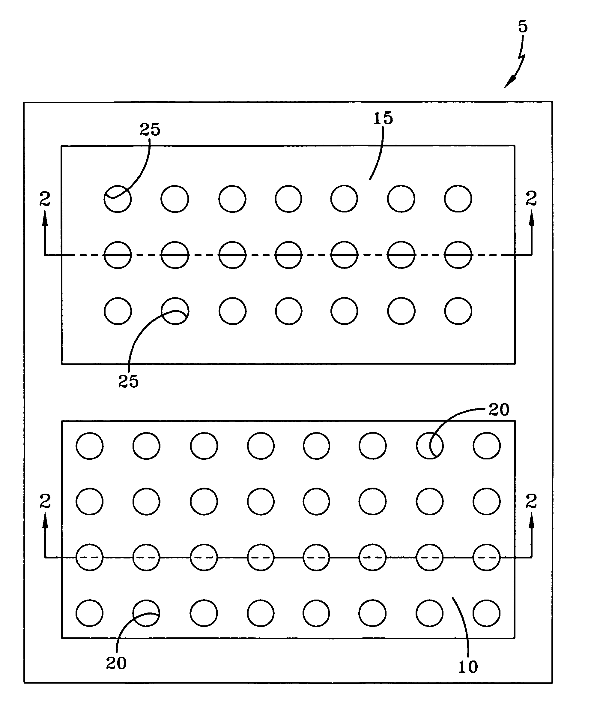
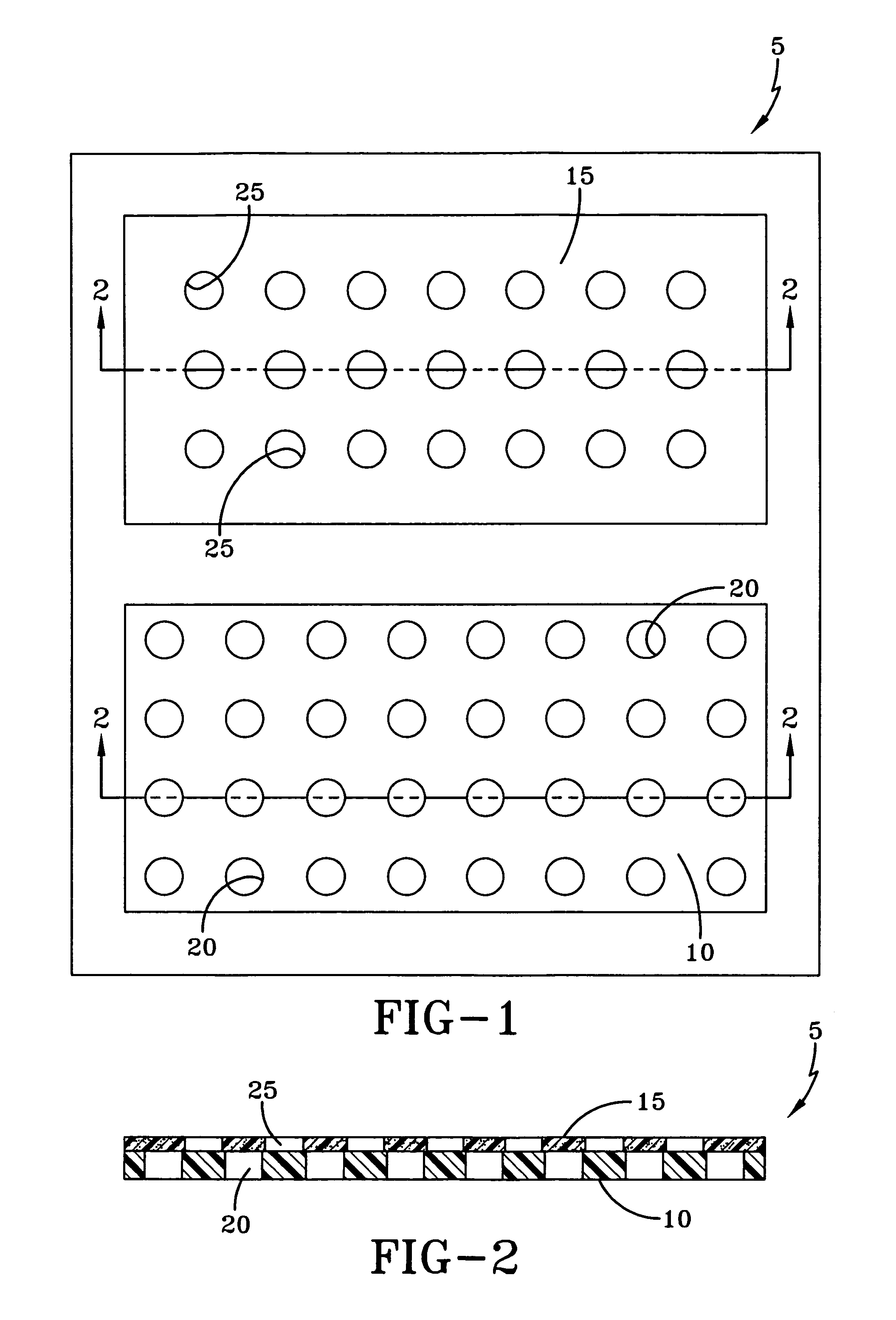
[0030]One embodiment of an impact and / or vibration absorbent material 5 of the present invention can be observed by reference to FIGS. 1–2. As can be seen in FIG. 1, two separate material layers 10, 15 are included in this particular material. The first (inner) layer 10 may be constructed from a number of flexible materials, such as polymeric materials and polymeric gel materials. Suitable materials may comprise, without limitation, silicone, urethane, and various other elastomers and thermoplastic elastomers. In this particular embodiment, the inner layer 10 of the impact and / or vibration absorbent material 5 is manufactured from a polymeric gel. Such a gel may be comprised of a block copolymer material, such as one of the family of block copolymer materials available from Kraton Polymers under the tradename of Kraton®. Of course, a number of other suitable materials are also available, and such would be known to those skilled in the art. Such materials are considered well-suited ...


PUM

PropertyMeasurementUnit
distanceaaaaaaaaaa
weightaaaaaaaaaa
sizeaaaaaaaaaa

Abstract

A testing apparatus and method for determining the impact an / or vibration absorbent characteristics of an impact and / or vibration absorbent material. The apparatus includes a base having upwardly extending vertical guide rods. A sample plate is maintained in a position above the base by one or more springs of known spring rate. A weight is adapted to move vertically along the guide rods and to impact the sample plate and a sample of impact and / or vibration absorbent material when dropped from a raised position. The impact of the weight causes a downward vertical displacement of the sample plate, which displacement is measured by a moveable indicator. This displacement can be used, along with the total spring rate provided by the spring(s), to calculate a pass-through impact force. The pass-through impact force can then be subtracted from the impact force generated by the falling weight to determine the amount of impact force absorbed by the impact and / or vibration absorbent material.

Description

[0001]This application is a continuation of U.S. application Ser. No. 11 / 084,906, filed on Mar. 21, 2005.BACKGROUND OF THE INVENTION[0002]The present invention is directed to an impact and / or vibration absorbent material and to a protective impact glove that incorporates said material. A testing apparatus that is particularly well-suited for determining the impact force absorption characteristics of such a material is also disclosed.[0003]Exposure of the human body to repeated impact and / or vibration is a known problem. Such exposure can occur in various settings: both occupational and recreational.[0004]It is known, for example, that extended exposure of the human body to vibration can lead to vascular, neurological and musculoskeletal disorders. The source of such vibration is commonly some type of mechanical device, such as a hand-held vibrating tool. In the case of exposure to hand-held vibrating tools, resultant disorders typically manifest in the body's upper limbs—such as in ...

Claims


Application Information

Patent Timeline
Patent Type & Authority Patents(United States)
IPC IPC(8): G01N7/00G01N3/00G01N33/00G01P15/00
CPCA41D19/01523A41D31/005A43B13/187A43B13/189A47C7/021B60N2/522B60N2/525B60N2/70F16F3/093F16F2230/36A41D31/285
Inventor HAMMONS, GARYKRAMER, ROGER W.MARKS, CHARLESPORTER, KEVINBOGARD, ROBERTSKAHILL, TRACISMITH, MARK
Owner HONDA MOTOR CO LTD
Why Eureka
Try Eureka