Method and apparatus for acoustic detection of a fluid leak behind a casing of a borehole

a technology of acoustic detection and casing, which is applied in the direction of instruments, borehole/well accessories, surveys, etc., can solve the problems of uncontrollable accumulation of gas, general gas leakage behind the casing, lack of zonal isolation,

Active Publication Date: 2007-05-22
SCHLUMBERGER TECH CORP
View PDF8 Cites 61 Cited by
  • Summary
  • Abstract
  • Description
  • Claims
  • Application Information

AI Technical Summary

Problems solved by technology

Gas leaks behind casing generally occur when a gas-bearing zone has not been properly isolated during the well construction process.
The lack of zonal isolation allows gas to flow from the gas-bearing zone to the surface or to another subterranean zone outside the casing.
The gas leak may for example cause an uncontrolled accumulation of gas behind the casing or at the surface of the well, and lead to a hazardous situations such as the contamination of a water table surrounding the well or the creation of an explosive mixture of gas at the surface.
The coarse frequency resolution and the time averaging limit the application of this type of tool to relatively high leak rates where the noise generated is semi-continuous and significant compared to background noise.

Method used


Image

  • Method and apparatus for acoustic detection of a fluid leak behind a casing of a borehole
  • Method and apparatus for acoustic detection of a fluid leak behind a casing of a borehole
  • Method and apparatus for acoustic detection of a fluid leak behind a casing of a borehole

Examples


Embodiment Construction

[0035]Same references will be used to reference the same elements in the Figures throughout the description.

General Overview

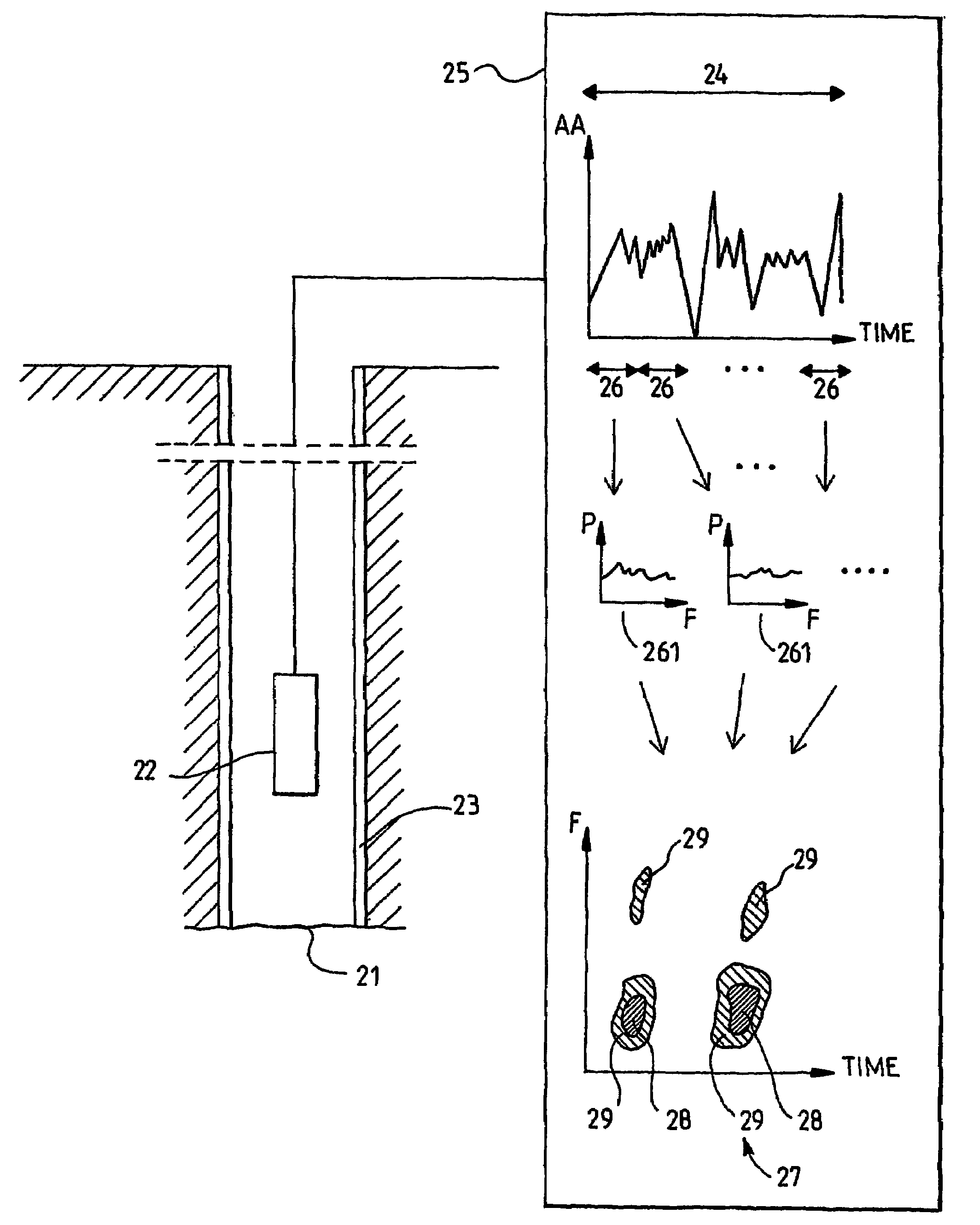
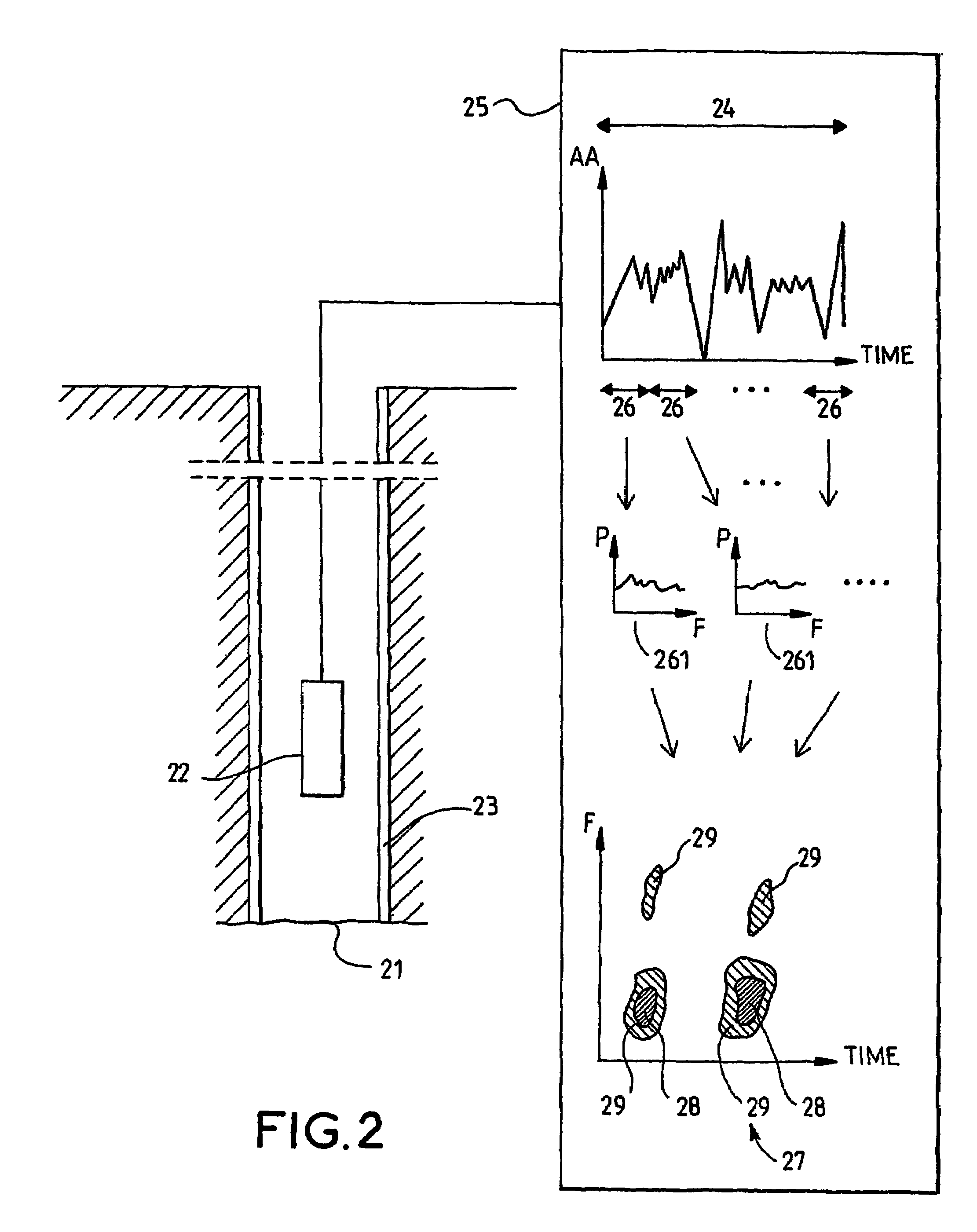
[0036]FIG. 2 provides an illustration of one example embodiment of the present invention. In this embodiment, passive noise recording is performed at a given depth in a borehole 21. A suitable noise detector 22 (hydrophone or geophone for example) is used to record Acoustic Amplitude (AA) for a given period of recording time 24.

[0037]The acoustic amplitude is recorded during one or a plurality of periods of recording time that generally have a duration adapted to be able to capture at least one acoustic event generated by a leak. The duration of the period of recording time 24 may for example have a value in a range from 10 to 30 seconds. The value may be decreased to 5 seconds or less for acoustic events that occur several times per second, and increased to several minutes for acoustic events that occur two or three times per minute. It is important that the r...


PUM


Abstract

An acoustic detection of a discrete acoustic signal allows to detect a leak behind a casing (23) of a borehole. An acoustic amplitude (AA) is sampled during a recording time period (24; 64) at a determined position along the tube. Time intervals (26; 66) are defined inside of the recording time period (24), and for each time interval (26) the measured acoustic amplitudes are processed to obtain respectively a corresponding power-frequency spectrum (261). A plurality of the power-frequency spectra are analyzed to identify the discrete acoustic signal by detecting time and frequency dependant changes of power. Preferably the processing involves a Fourier transform analysis. A power-frequency time plot is used to conveniently identify the discrete acoustic event.

Description

TECHNICAL FIELD[0001]The invention relates to the field of acoustic investigation techniques used in wells.BACKGROUND OF THE INVENTION[0002]Acoustic investigation techniques are widely used as non-destructive tools to check the integrity of wells and their casing. As an example, noise logging has been used for almost 30 years to detect the location of gas leaks behind a casing of a well.[0003]Gas leaks behind casing generally occur when a gas-bearing zone has not been properly isolated during the well construction process. The lack of zonal isolation allows gas to flow from the gas-bearing zone to the surface or to another subterranean zone outside the casing. The gas leak may for example cause an uncontrolled accumulation of gas behind the casing or at the surface of the well, and lead to a hazardous situations such as the contamination of a water table surrounding the well or the creation of an explosive mixture of gas at the surface.[0004]Turning now to FIG. 1, a schematic diagra...

Claims


Application Information

Patent Timeline
Patent Type & Authority Patents(United States)
IPC IPC(8): G01V1/00E21B47/10G01V1/50
CPCE21B47/101G01V1/50E21B47/107
Inventor JAMES, SIMONFITZGERALD, PETER
Owner SCHLUMBERGER TECH CORP
Why Eureka
Try Eureka