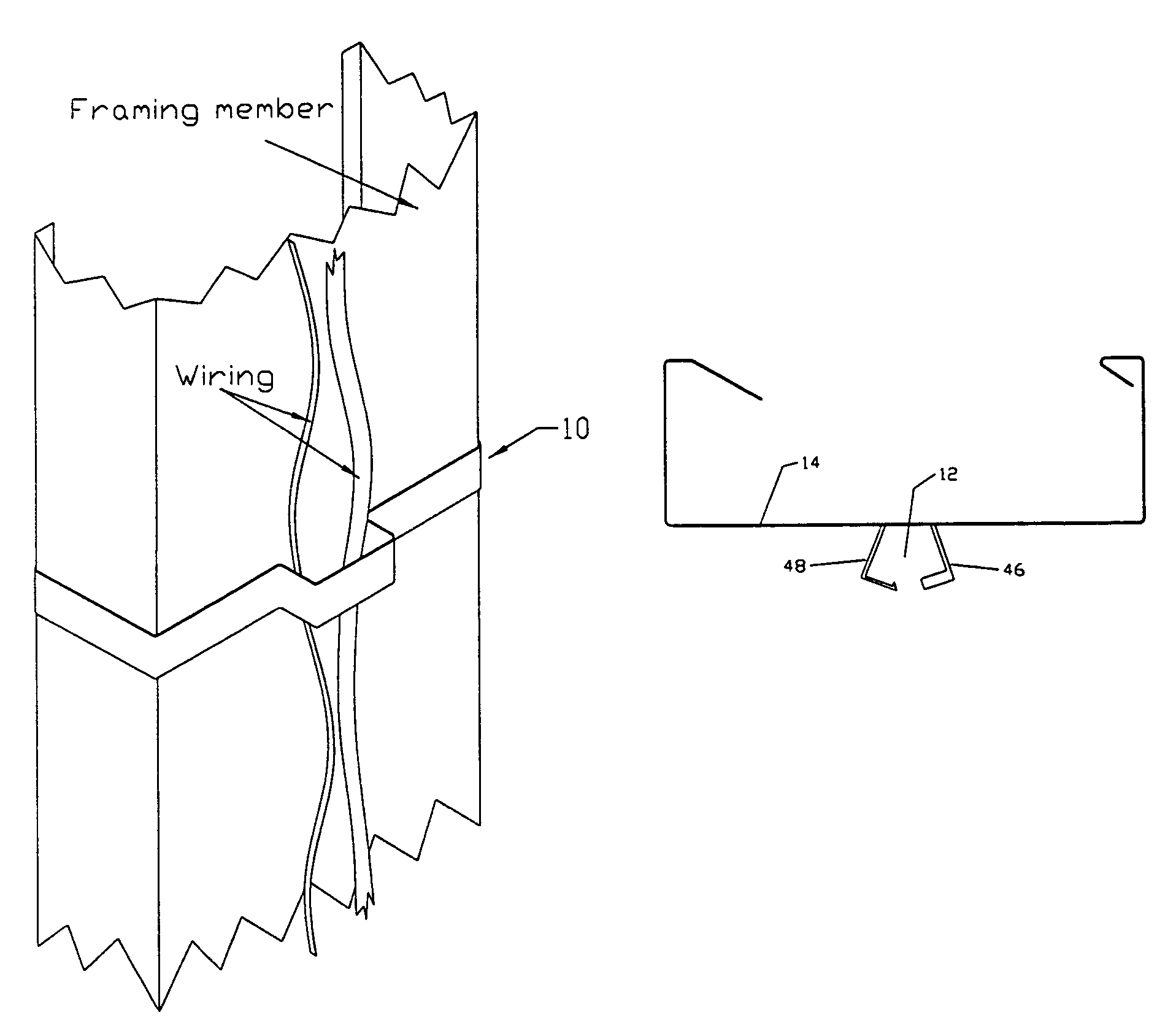
Wiring clip securing electrical wiring to a framing member

a technology of wire clip and metal frame, which is applied in the direction of electrical cable suspension arrangement, light support device, candle holder, etc., can solve the problems of difficult stapling of electrical wires to metal frame, and insufficient support for electrical wiring

Inactive Publication Date: 2007-05-22
COLLETT DENISE MARIE
View PDF52 Cites 36 Cited by
  • Summary
  • Abstract
  • Description
  • Claims
  • Application Information

AI Technical Summary

Problems solved by technology

While the method is suitable for single wires, this becomes a particular problem for multiple wires, where the wires should be stapled one on top of the other to maintain the proper distance from the nearest edge of the framing member.
Additionally, with the increasing usage of metal studs as framing members, the stapling of the electrical wires to metal framing member is difficult and may not provide adequate support for the electrical wiring.

Method used


Image

  • Wiring clip securing electrical wiring to a framing member
  • Wiring clip securing electrical wiring to a framing member

Examples


Embodiment Construction

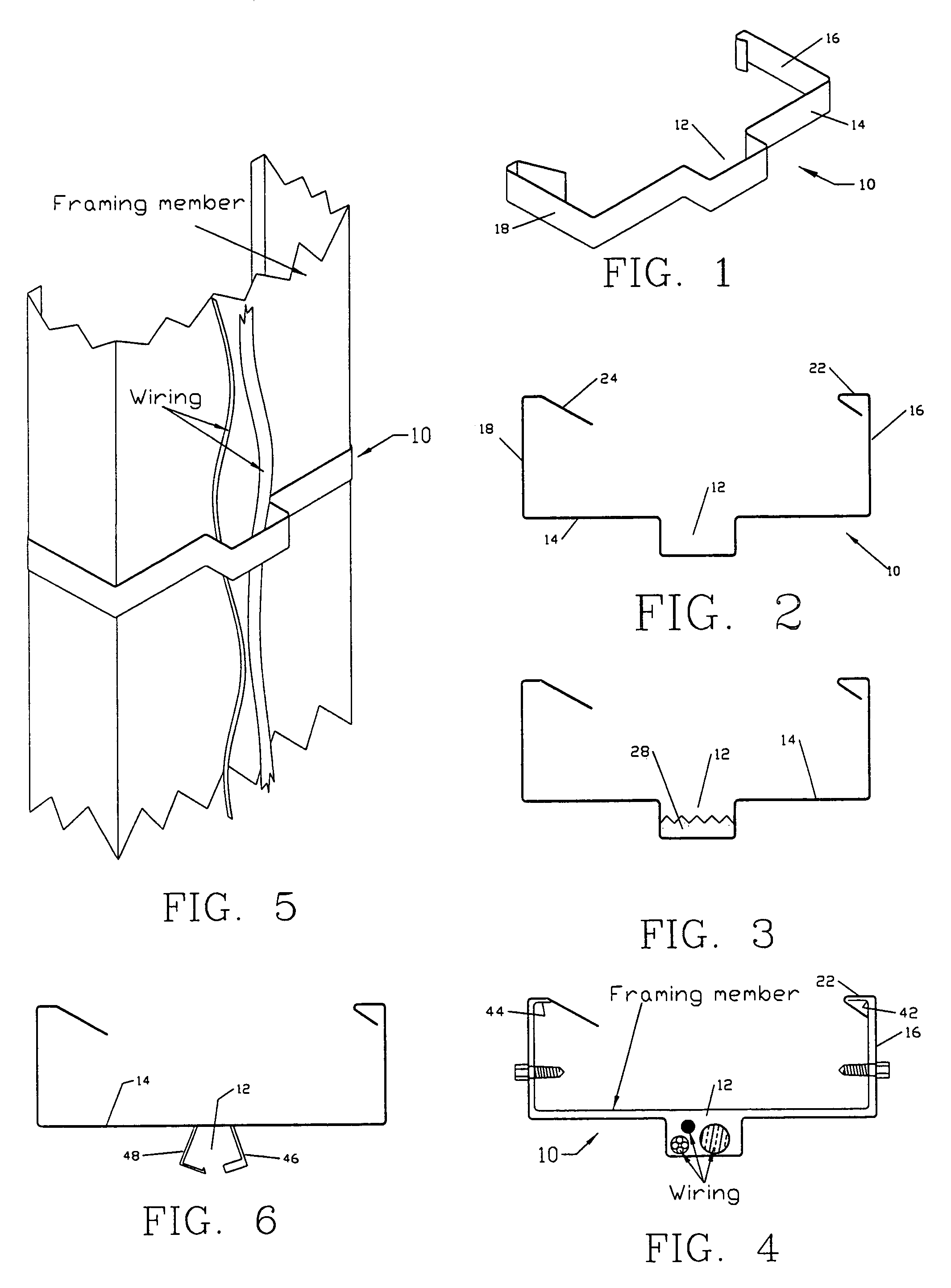
[0016]Referring to FIGS. 1 and 2, an embodiment of the subject wiring clip 10 generally resembles an open frame having a wire receiving area 12 formed in the main body 14, where the wire receiving area 12 is centrally located within the main body 14. Although centrally locating wire receiving area 12 is preferred, a non-centrally located wire receiving area can also be utilized. The wire clip 10 shown in FIGS. 1 and 2 has a generally U-shaped configuration, with two arms 16 and 18 being joined to the main body 14. The end 20 of the first arm 16 is bent to form a J-hook 22, such that the J-hook 22 can be hooked about a first inner edge 42 of a metal framing member. The end 24 of the second arm 18 can be bent such that it can be slipped around a second inner edge 44 of the metal framing member. As such, end 24 can be removably secured about the second inner edge 44 of the metal framing member. The arms 16 and 18, as well as the main body 14, are preferably flexible, such that the arms...


PUM


Abstract

A wiring clip for securing electrical wiring to metal framing members. In a specific embodiment, the subject clip can secure the wiring a required distance from the nearest edge or face of the metal framing member to which a wall board is to be secured. The wire clip generally resembles an open frame having a wire receiving area formed in the main body, where the wire receiving area is centrally located within the main body. The wire clip is generally of U-shaped configuration, with two arms being joined to the main body. The end of the first arm is bent to form a J-hook, such that the J-hook can be hooked about a first inner edge of a metal stud. The end of the second arm comprises a clip, such that the clip can be removable, secured about the second inner edge of the metal stud. The arms, as well as the main body, are resilient, such that the arms and the main body will embrace the metal stud.

Description

FIELD OF THE INVENTION[0001]The present invention relates generally to a wiring clip, and more particularly to a wiring clip for securing electrical wiring to a metal framing member.BACKGROUND OF THE INVENTION[0002]The National Electric Code specifies that electrical wiring be positioned a defined safe distance (1¼ inches) from the nearest edge of a framing member. The code requirement is found in Article 300, Section 300-4(d) N.E.C. If such spacing can not be maintained, the electrical wiring has to be protected by a 1 / 16 inch thick steel plate or sleeve. The purpose of the code requirement is to prevent fasteners, intend to be driven into the face of the framing member to secure the wall board to the framing member, from piercing or otherwise damaging the electrical wiring.[0003]A present practice is to staple electrical wiring to the major flat side of a wood framing member. While the method is suitable for single wires, this becomes a particular problem for multiple wires, where...

Claims


Application Information

Patent Timeline
Patent Type & Authority Patents(United States)
IPC IPC(8): F16L3/22
CPCF16L3/04H02G3/32
Inventor COLLETT, II, MAURY E.
Owner COLLETT DENISE MARIE
Why Eureka
Try Eureka