Fluid-filled vibration damping bushing

a technology of vibration damping bushing and fluid filling, which is applied in the direction of shock absorbers, machine supports, mechanical equipment, etc., can solve the problems of higher cost of fluid filling vibration damping bushing, deformation and unstable shape of base rubber, etc., and achieves the effect of convenient attachment and convenient positioning

Inactive Publication Date: 2007-05-22
SUMITOMO RIKO CO LTD
View PDF28 Cites 19 Cited by
  • Summary
  • Abstract
  • Description
  • Claims
  • Application Information

AI Technical Summary

Benefits of technology

[0021]It is an object of the present invention to provide a fluid-filled vibration damping bushing that ensures the required vibration isolating or damping ability and stopper ability, while reducing the number of vulcanized parts required overall and the resultant manufacturing cost.
[0023]A first mode of the invention provides a fluid-filled vibration damping bushing comprising: (I) a bushing body having an inner tubular metal member, an outer peripheral sleeve disposed coaxially about the inner tubular metal and a base rubber interposed between and elastically connected the inner tubular metal member and the outer peripheral sleeve, the base rubber having a pair of depressions recessed towards an inner tubular metal member side and open in an outer circumferential surface of the base rubber, so as to provide mutually independent first and second fluid chambers having a non-compressible fluid sealed therein, and the outer peripheral sleeve having a pair of aperture window of shape corresponding to openings of the first and second fluid chamber; (II) an orifice member at least partially defining an orifice passage extending between the openings of the first and second fluid chamber so that the fluid sealed within the first and second fluid chambers is caused to flow between the chambers; (III) an outer tubular metal member having a seal rubber layer integrally bonded by vulcanization to an inner circumferential surface thereof for liquid-tight sealing of the first and second fluid chambers, and fastened to an outer circumferential surface of the outer peripheral sleeve via the seal rubber layer, closing off the opening of the first and second fluid chambers; and (IV) a stopper rubber constituted as a separate element from the base rubber, disposed at a circumferential location corresponding at a minimum to either the first or second fluid chamber, for restricting relative displacement of the inner tubular metal member and outer tubular metal member in the axis-perpendicular direction, wherein the stopper rubber is formed separately from the orifice member and is bonded to a first axial end portion of the outer tubular metal member at a location outside the first and second fluid chambers so as to face toward the inner tubular member, and the outer tubular metal member with the stopper rubber attached thereto is inserted onto the bush body from an other axial end thereof.
[0028]According to the present invention, as described hereinabove, the stopper rubber formed separately from the orifice member, is integrally bonded (by vulcanization, for example) facing the inner tubular metal member in an exposed state at the axial end of the outer tubular metal member situated to the outside of the fluid chambers and outwardly in axial direction of the base rubber. Therefore, two components, namely, a rubber unitary vulcanized part consisting of the bushing body, and an unitary vulcanized part composed of the outer tubular metal member, the seal rubber layer, and the stopper rubber, suffice, whereby the number of vulcanized parts may be reduced as compared to the prior art, so that the costs associated with the fluid-filled vibration damping bushing can be lowered.
[0031]Where the stopper member is integrally bonded by vulcanization to the orifice member as in the past, overall thickness increases, whereby it becomes impossible in actual practice to attach the orifice member by inserting it, together with the rubber stopper, into the base rubber in the axial direction. With the present invention on the other hand, since the stopper rubber is provided outside the fluid chamber in a form separated from the orifice member, it becomes possible for the orifice member to be of unitary construction continuous in the circumferential direction, and to be attached to the base rubber in the axial direction. In this instance, the orifice member, which in the past was constructed of two separate parts, can now be constituted as a single component, whereby it becomes possible to further lower the cost of the fluid-filled vibration damping bushing.
[0033]According to the fourth mode, on the other hand, the orifice member constitutes the unitary structure of C ring shape continuous in the circumferential direction, the gap between the circumferential ends of the bushing body adjacent to the first fluid chamber and the second fluid chamber is smaller than the gap between the circumferential ends of the orifice member, and the orifice member is attached by being inserted into the bushing body in the axis-perpendicular direction. Even with this arrangement, the orifice member can be constituted as an unitary structure and attached easily to the bushing body.
[0034]In the present invention, the bushing body in the out tubular metal member, more specifically a portion situated at an axial end of the outer peripheral sleeve, constitutes a shoulder portion facing the inner tubular metal member side, and this is made to contact an axial end of the outer peripheral sleeve, with the stopper rubber integrally vulcanization bonded to the inner circumferential surface of the small-diameter portion continuing on from the shoulder portion (Fifth Mode). By means of this arrangement, the gap between the inner tubular metal member and the stopper rubber can readily be given the appropriate spacing needed for stopper action. Additionally, when the outer tubular metal member is fitted externally onto the bushing body, the relative positional relationship of the bushing body and the outer tubular metal member can be readily positioned.

Problems solved by technology

However, in this instance, the problem of appreciable deformation and unstable shape of the base rubber can occur, and additional problems, such as to the need to for additional process after press-metal member in order subsequently bond the base rubber 202 and the outer tubular metal member 214 (secondary vulcanization), and the need for a subsequent process to seal the liquid in the fluid chambers 204-1, 204-2, occur as well.
However, where the stopper rubbers 222-1, 222-2 are constituted separately from the base rubber 202 and designed to be attached to the base rubber 202, the fluid-filled vibration damping bushing requires a greater number of vulcanized parts (vulcanized rubber components) (here, four vulcanized parts are required), as a result of which the problem of higher cost of the fluid-filled vibration damping bushing occurs.
While a number of problems pertaining to fluid-filled vibration damping bushings used as suspension bushings have been mentioned above, fluid-filled vibration damping bushings of this kind are used widely at various locations, with similar problems occurring in these instances as well.
However, JP-A-2003-269507 does not teach a vibration damping bushing of fluid-filled, thereby being directed instead to a different purpose.

Method used


Image

  • Fluid-filled vibration damping bushing
  • Fluid-filled vibration damping bushing
  • Fluid-filled vibration damping bushing

Examples


Embodiment Construction

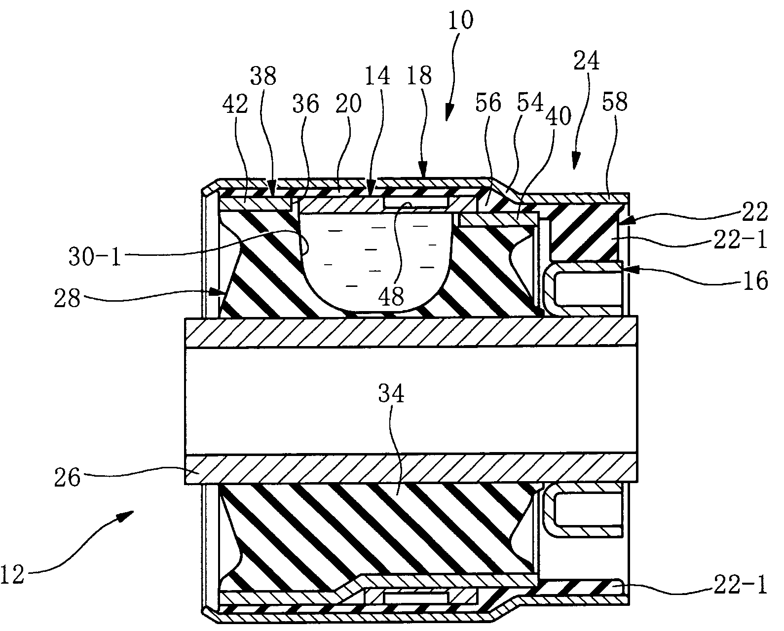
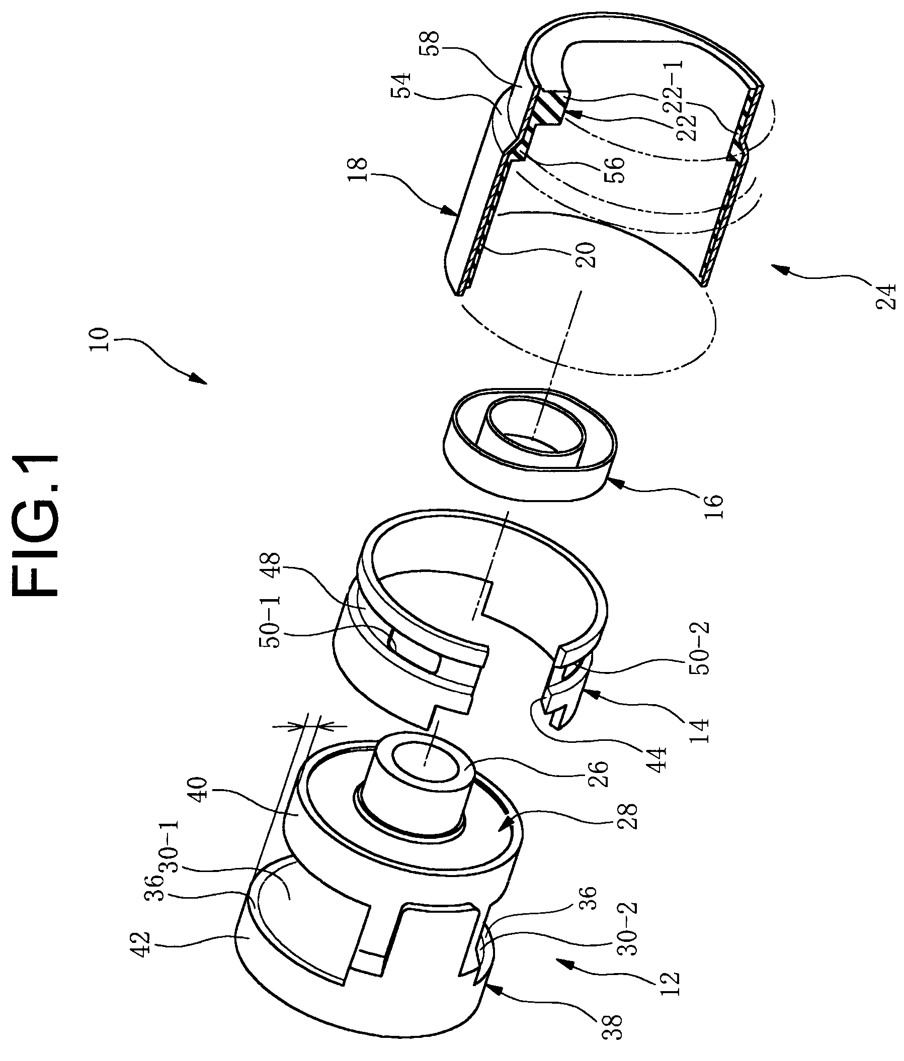
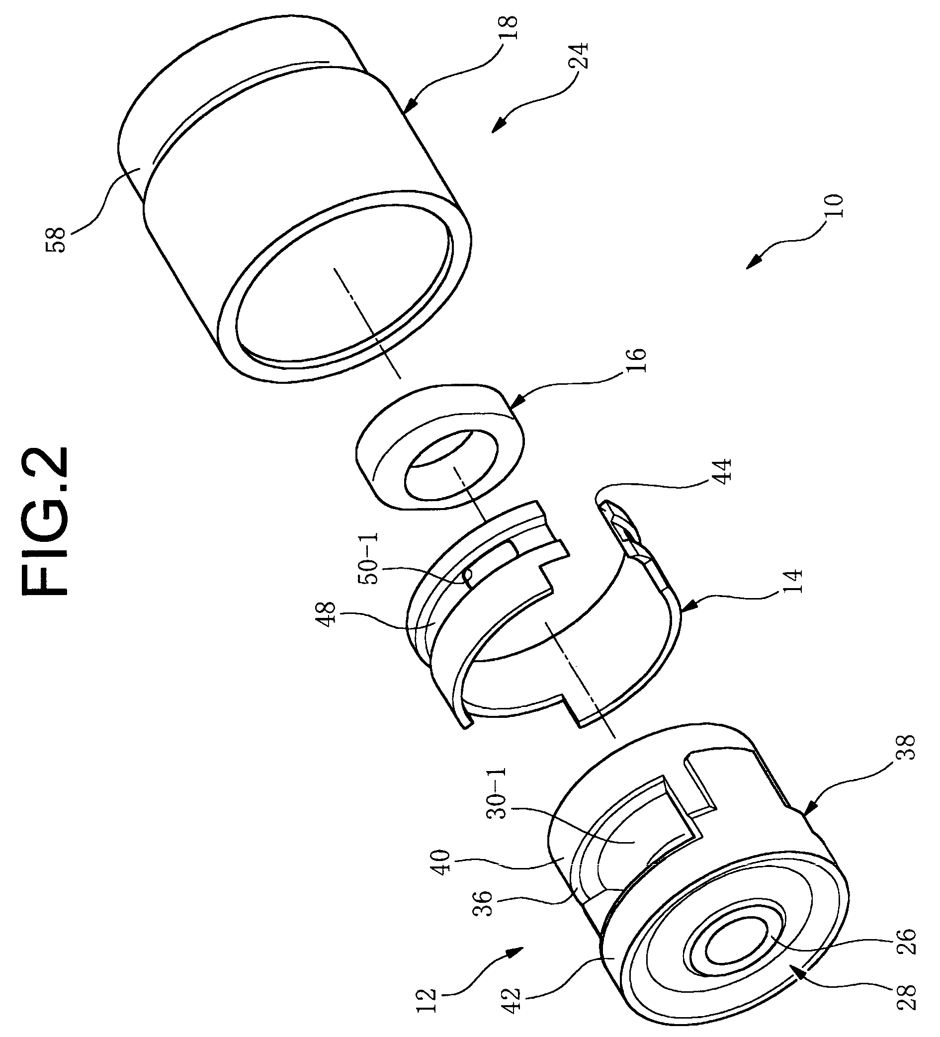
[0054]FIGS. 1–3 show a fluid-filled vibration damping bushing 10 for use as a suspension bushing or the like. In this embodiment, the fluid-filled vibration damping bushing 10 includes a first integrally vulcanized unit in the form of a bushing body 12, an orifice metal member 14, a stopper metal member 16 serving as a stroke distance adjusting structure, and a second integrally vulcanized unit 24 composed of a seal rubber layer 20 and a stopper rubber 22 integrally vulcanization bonded to an outer tubular metal member 18.

[0055]As shown in FIGS. 4, 5A and 5B, the bushing body 12 has an inner tubular metal member 26 of round tubular shape, which is formed by cutting an extruded metallic pipe, for example, and a base rubber 28 integrally bonded by vulcanization onto an outer circumferential surface of the inner tubular metal member 26. On the base rubber 28 are formed a mutually independent first fluid chamber 30-1 and second fluid chamber 30-2 (hereinafter termed simply fluid chamber...


PUM


Abstract

A fluid-filled vibration damping bushing including an inner tubular metal member and an outer peripheral sleeve elastically connected via a base rubber interposed therebetween with first and second fluid chambers formed therein. A stopper rubber constituted as a separate element from the base rubber, disposed at a circumferential location corresponding at a minimum to either the first or second fluid chamber, for restricting relative displacement of the inner tubular metal member and outer tubular metal member in an axis-perpendicular direction. The stopper rubber is formed separately from an orifice member and bonded to one axial end portion of the outer tubular metal member at a location outside the first and second fluid chambers so as to face toward the inner tubular member. The outer tubular metal member with the stopper rubber attached thereto is inserted onto the outer peripheral sleeve from the other axial end thereof.

Description

INCORPORATED BY REFERENCE[0001]The disclosure of Japanese Patent Application No. 2004-202406 filed on Jul. 8, 2004 including the specification, drawings and abstract is incorporated herein by reference in its entirety.BACKGROUND OF THE INVENTION[0002]1. Field of the Invention[0003]This invention relates to a fluid-filled vibration damping bushing suitable for use as an automotive suspension bushing or other application.[0004]2. Description of the Related Art[0005]In automotive suspensions to date, a vibration damping rubber is interposed between an suspension arm and a linking portion to a body side, to absorb vibration between the suspension arm and the body side. Conventionally, a tubular mounting type suspension bushing was used as a suspension bushing of this kind, so as to be able to absorb vibration while ensuring oscillation of the suspension arm. An example of a vibration damping bushing for use as a suspension bushing of this kind is depicted in FIGS. 16–18. The illustrated...

Claims


Application Information

Patent Timeline
Patent Type & Authority Patents(United States)
IPC IPC(8): F16F5/00F16F13/00F16F15/00F16F9/00F16M5/00
CPCF16F13/1445F16F13/1463
Inventor KATO, KAZUHIKO
Owner SUMITOMO RIKO CO LTD
Why Eureka
Try Eureka