Clamp for elongated objects such as pipe

a technology for elongated objects and clamps, which is applied to screwdrivers, threaded fasteners, machine supports, etc., can solve the problems of increasing the number of assembly steps, increasing the cost of finished products, and increasing the number of manufacturing dies, so as to reduce the transmission of vibration, reduce the shape, and reduce the effect of transmission

Inactive Publication Date: 2007-05-22
NEWFREY
View PDF18 Cites 39 Cited by
  • Summary
  • Abstract
  • Description
  • Claims
  • Application Information

AI Technical Summary

Benefits of technology

[0009]Accordingly, an object of the present invention is to provide a clamp for elongated objects such as pipe, in which the vibration absorbing mechanism for reducing the transmission of vibration between an elongated object and a support can be realized in a simple shape, and can reduce the transmission not only of vibration in the circumferential direction relative to the elongated object, but also of vibration having a component in the axial direction of the elongated object.
[0010]In a preferred, but non-limiting embodiment of the present invention, a clamp for an elongated object comprises a gripper unit for holding an elongated object such as a pipe or wire harness, and a securing unit for attachment to a support such as a body panel. The clamp is configured such that the elongated object is attached to the support by the elongated object being held by the gripper unit, and by the securing unit being attached to the support. A vibration absorbing unit is provided between the gripper unit and the securing unit, for reducing the transmission of vibration between the gripper unit and the securing unit. The vibration absorbing unit can bend in directions in which the gripper unit and the securing unit move relative to one another. The vibration absorbing unit includes a pair of first flexible curved arms and pairs of second flexible curved arms, the first curved arms and the second curved arms being superposed between the gripper unit and the securing unit, and being arranged so that bending directions thereof cross.
[0011]In this embodiment, no elastic soft material layer is required. The vibration absorbing mechanism of the invention can be realized in a simple shape; die costs can be held down to a low level; and the transmission not only of vibration in the circumferential direction relative to the elongated object such as pipe, but also of vibration having a component in the axial direction of the elongated object can be reduced.
[0012]In the elongated-object clamp described above, it is preferable that the gripper unit comprise a curved receptacle for accepting at least half of the circumference of a side surface of the elongated object, and an elastic holding piece for pressing, from above, a side surface of the elongated object in the curved receptacle, and that the securing unit comprise a shaft which extends below the gripper unit, shaped for attachment to the support. It is further preferable that the first curved arms and the second curved arms be arranged so that they cross at an angle of 90 degrees, so that the directions of bending are perpendicular to one another, so that one of the sets of curved arms can reduce the transmission of vibration in the circumferential direction relative to the elongated object, and the other set of curved arms can reduce the transmission of vibration having a component in the axial direction of the elongated object, whereby vibration in all directions can be absorbed.
[0013]In the elongated-object clamp described above, furthermore, it is preferable that the first curved arms be arranged on the underside of the gripper unit and that the second curved arms be arranged on the upper side of the securing unit, and that a regulating member be formed between the securing unit and the gripper unit, extending between the pairs of second curved arms to a position adjacent to the underside of the gripper unit, for regulating the amount of movement of the arms so that the range of movement of the elongated object can be regulated. The regulating member is preferably a T-shaped member having a rod-shaped part which extends upward from the upper part of the securing unit and a horizontal part positioned adjacent to the underside of the gripper unit and extending to both sides in the width direction of the gripper unit.
[0014]In the elongated-object clamp described above, moreover, it is preferable that the horizontal part of the T-shaped regulating member be accommodated inside a frame part which extends below the gripper unit so as to prevent the gripper unit from becoming detached from the securing unit even if the first curved arms or second curved arms are damaged due to an impact or the like. Thus, the elongated object can be prevented from falling away from the support.

Problems solved by technology

When an elastic soft material layer is used as the vibration absorbing mechanism, in order to secure the elastic soft material layer to the gripper unit the number of manufacturing dies increases as compared to when no elastic soft material layer is used; the cost of the finished product increases, and the number of assembly steps increases.
With the vibration absorbing mechanism in the above-mentioned U.S. Patent, the curved arms between the gripper unit and the securing unit contribute to the absorption of vibration in the circumferential direction relative to the pipe, but are not suitable for absorbing vibration in directions other than the circumferential direction relative to the pipe (e.g., pipe axial direction).
If the curved arms are damaged, there is a danger of the pipe falling away from the support.
With the vibration absorbing mechanism in the above-mentioned Japanese application, the bendable curved holding pieces are complexly erected from the bottom surface of the gripper unit; the manufacturing dies become complex; and finished product costs are increased.
Also, the three spiraling coupling plates provided in the vibration absorbing mechanism between the securing unit attached to a stud on a panel and the base supporting the gripper unit, further complicate the dies, and finished product costs are increased.
Furthermore, when those vibration absorbing mechanisms are damaged, there is a danger of the pipe falling away from the clamp.

Method used


Image

  • Clamp for elongated objects such as pipe
  • Clamp for elongated objects such as pipe
  • Clamp for elongated objects such as pipe

Examples


Embodiment Construction

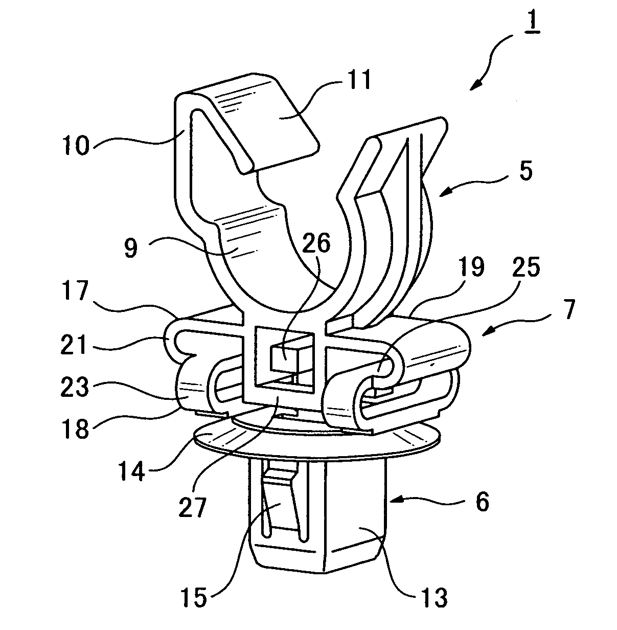
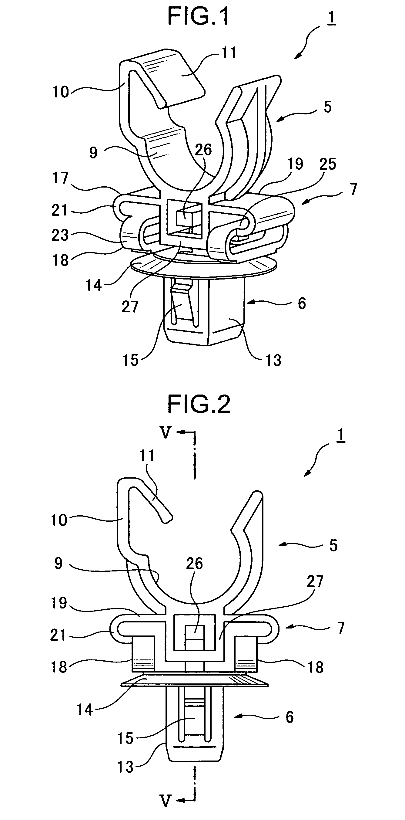
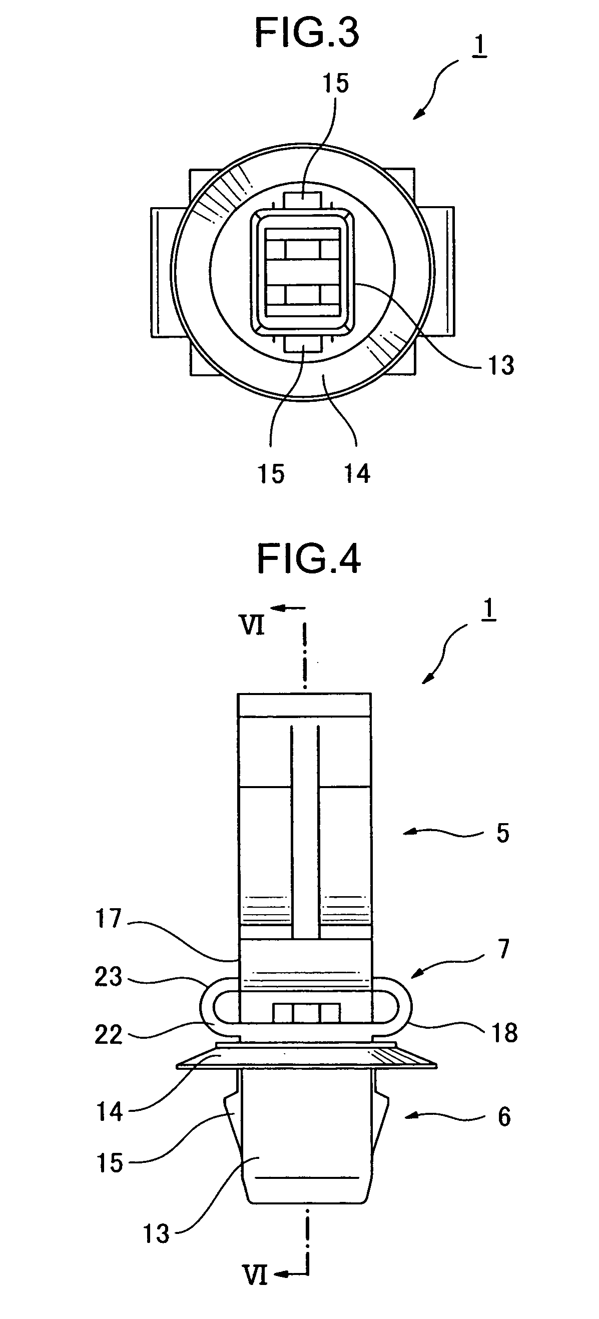
[0024]In a preferred embodiment shown in FIGS. 1 to 6, an elongated-object clamp 1 is integrally molded of a hard synthetic resin. The elongated-object clamp 1 does not employ an elastic soft material layer for reducing the transmission of vibration between a pipe 2 and a body panel 3 (see FIGS. 7 and 8). The elongated-object clamp 1 comprises a gripper unit 5 (or several gripper units) for holding an elongated object such as the pipe 2 or a wire harness or the like, a securing unit 6 for attaching the elongated-object clamp 1 to a support such as the body panel 3, and a vibration absorbing unit 7, arranged between the gripper unit 5 and the securing unit 6, for reducing the transmission of vibration between the gripper unit 5 and the securing unit 6. The gripper unit 5 comprises at least one flexible curved receptacle 9 for accepting at least half of the circumference of a side surface of the pipe 2, and an elastic holding piece 11 for pressing, from above, a side surface of the pi...


PUM


Abstract

An elongated object clamp 1 which reduces transmission of vibration between an object 2 and a support 3 in a circumferential direction of the object and an axial direction comprises a gripper unit 5 for holding an elongated object such as a pipe, a securing unit for attaching the clamp to a support such as a body panel, and a vibration absorbing unit 7 for reducing transmission of vibration between the gripper unit and the securing unit. The vibration absorbing unit can bend in various directions and includes first curved arms and second curved arms stacked between the gripper unit and the securing unit, and arranged so that bending directions of the arms cross one another.

Description

CROSS-REFERENCE TO RELATED APPLICATION[0001]This application claims the benefit of Japanese Patent Application No. 2003-428681 filed Dec. 25, 2003, incorporated herein by reference.BACKGROUND OF THE INVENTION[0002]This invention relates to a clamp for elongated objects, which comprises a gripper unit for holding elongated objects such as pipe or wire harnesses, and a securing unit for attachment to a support such as a body panel, configured such that the elongated object is held in the gripper unit, the securing unit is attached to the support, and, thereby, the elongated object is attached to the support.[0003]Clamps for elongated objects are known which comprise a gripper unit for holding elongated objects such as pipe or wire harnesses and a securing unit for attachment to a support such as a body panel. The elongated object is held in the gripper unit, and the securing unit is attached to the support, whereby the elongated object is attached to the support. When an elongated obj...

Claims


Application Information

Patent Timeline
Patent Type & Authority Patents(United States)
IPC IPC(8): F16L3/08B60R16/02F16L3/12F16B5/12F16B19/00F16F15/04F16L3/13F16L55/035H02G3/30H02G3/32
CPCB60R16/0207F16L3/13F16L55/035H02G3/32
Inventor KATO, HIROYUKI
Owner NEWFREY
Why Eureka
Try Eureka