
Pre-stressed tie rod and method of manufacture

a technology of tensioned tie rods and manufacturing methods, which is applied in the direction of manufacturing tools, applications, press rams, etc., can solve the problems of high energy costs, short coming of direct force injection molding machines, and high energy costs for molding operations, etc., and achieves the effect of convenient us

Inactive Publication Date: 2007-05-22
FORCE PRO
View PDF13 Cites 30 Cited by
  • Summary
  • Abstract
  • Description
  • Claims
  • Application Information

AI Technical Summary

Benefits of technology

[0022]Due to the shortcomings of the prior art, it is an objective of the present invention to provide a pre-stressed tie rod which is easy to use.
[0026]It is still another objective of the present invention to provide a pre-stressed tie rod which can be used on a traditional press, thus providing the same capacity while reducing the amount of metal or other material used to construct the frame of the press.

Problems solved by technology

If it is not the plastic will seep between the two halves of the mold and cause the parts being formed to flash.
The greatest short coming of the direct force injection molding machine is the high energy costs.
This translates into higher energy costs to run the molding operation.
The primary limiting factors in the ability of a restrained force injection molding machine is the capacity of the tie rods.
However, heretofore use of pre-stressed tie rods on injection molding machines is not known.
The capacity of the press for exerting force on the work piece is limited by the tensile strength of the tie rods.
The force exerted by this arrangement can be difficult to gauge and balance as well as adjust.
This oftentimes leads to less than optimal use of the device.
1. The shortcomings of the prior art tie rods did not allow for the use of pre-stressed tie rods on an injection molding machi
As can be seen by the equation, one of the limiting factors in determining the deflection is the length of the tie rod.
This in turn limits the height of the piece which can be formed.
For this reason, restrained force injection molding machine such as the one shown in FIG. 1 have been limited to applications such as molding pallets or other short or flat objects.
This limitation has prevented them from being used to mold taller objects such as traffic barrels.

Method used


Image

  • Pre-stressed tie rod and method of manufacture
  • Pre-stressed tie rod and method of manufacture
  • Pre-stressed tie rod and method of manufacture

Examples


Embodiment Construction

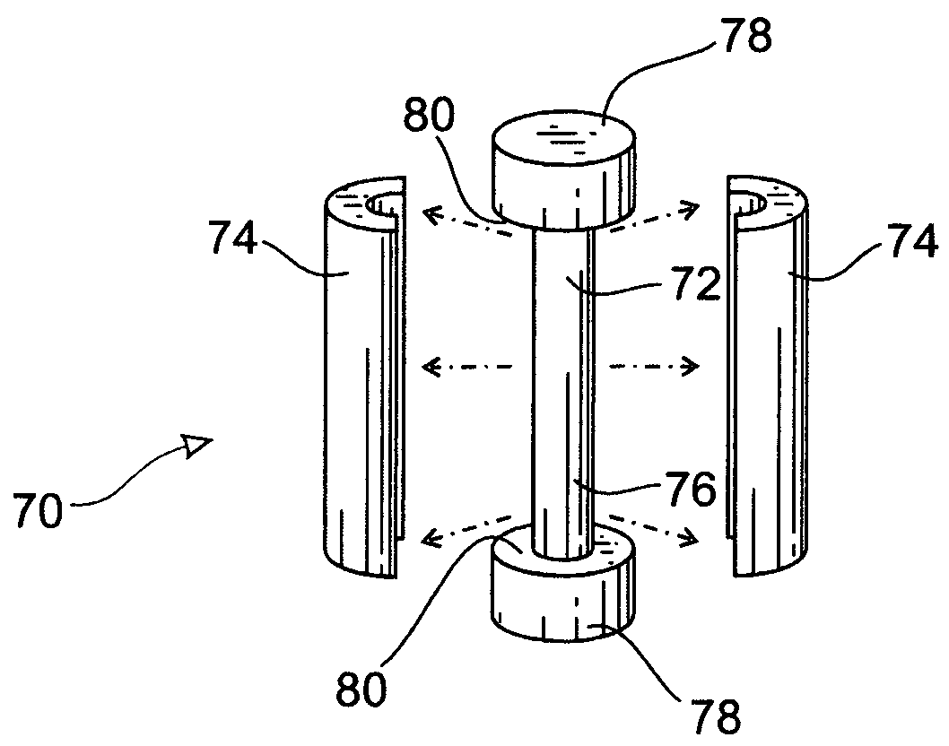
[0037]FIG. 3 shows a top view of the preferred embodiment of the improved tie rod 70. FIG. 4 shows a cross-sectional view of the same tie rod 70 taken along the line 4—4, shown in FIG. 3. The same tie rod is shown in an exploded view in FIG. 5. The improved tie rod has a center 72, which is surrounded by an compression sleeve 74. In the preferred embodiment, the center 72 generally has a dumbbell shape, comprising an elongated tensioned core 76 connecting two bases 78. Each base 78 has a shoulder 80 located on the side of the base facing the opposing base 78.

[0038]The compression sleeve 74 in its preferred embodiment shown in FIGS. 3, 4 and 5, is constructed from two elongated semi-circular pieces, as best seen in FIG. 5. It should be noted that while the preferred embodiment of the pre-stressed tie rod 70 is shown in FIGS. 3, 4 and 5, other geometric configurations could also be used to achieve the same result and thus should be considered to fall within the scope of the present in...


PUM

PropertyMeasurementUnit
Lengthaaaaaaaaaa
Forceaaaaaaaaaa

Abstract

The present invention relates to a pre-stressed tie rod and method of manufacture. The pre-stressed tie rod can be used on injection molding machines to increase the length of the tie rod and movement of the platen, wherein the tie rods are loaded to restrict mold separation. The pre-stressed tie rods could also be used with other types of presses.

Description

[0001]This application claims priority of U.S. provisional patent application Ser. No. 60 / 548,412, entitled “Pre-Stressed Tie Rod and Method of Manufacture,” by Bryan R. Kirchmer and Derek Campbell, and having a filing date of Feb. 28, 2004, the description of which is incorporated herein by reference.BACKGROUND OF THE INVENTION[0002]1. Field of the Invention[0003]This invention relates to a new and improved pre-stressed tie rod and a method of manufacturing the same. More particularly, this invention is directed toward use of an improved pre-stressed tie rod to increase the capacity of plastic molding machines to mold larger parts. Still more particularly, the present invention can also be applied to other types of devices such as presses.[0004]2. Prior Art[0005]Injection molding machines are categorized by the amount of force they are able to exert on a work piece or molding dies. Generally speaking Injection molding machines fall into two types. The first type, the direct force i...

Claims


Application Information

Patent Timeline
IPC IPC(8): B29C45/64B23P11/02B30B15/04
CPCB23P11/025Y10T29/49874Y10T29/49865
Inventor KIRCHMER, BRYAN R.CAMPBELL, DEREK
Owner FORCE PRO
Features
  • Generate Ideas
  • Intellectual Property
  • Life Sciences
  • Materials
  • Tech Scout
  • Unparalleled Data Quality
  • Higher Quality Content
  • 60% Fewer Hallucinations
Learn More