
Feeder for endless welding wire

a feeder and wire technology, applied in the field of endless feeders, can solve the problems of reducing the head space of the feeder, affecting the welding effect, and affecting the quality of the feed wire, so as to reduce tangles and other physical problems, and reduce the effect of head spa

Active Publication Date: 2007-05-22
LINCOLN GLOBAL INC
View PDF8 Cites 35 Cited by
  • Summary
  • Abstract
  • Description
  • Claims
  • Application Information

AI Technical Summary

Benefits of technology

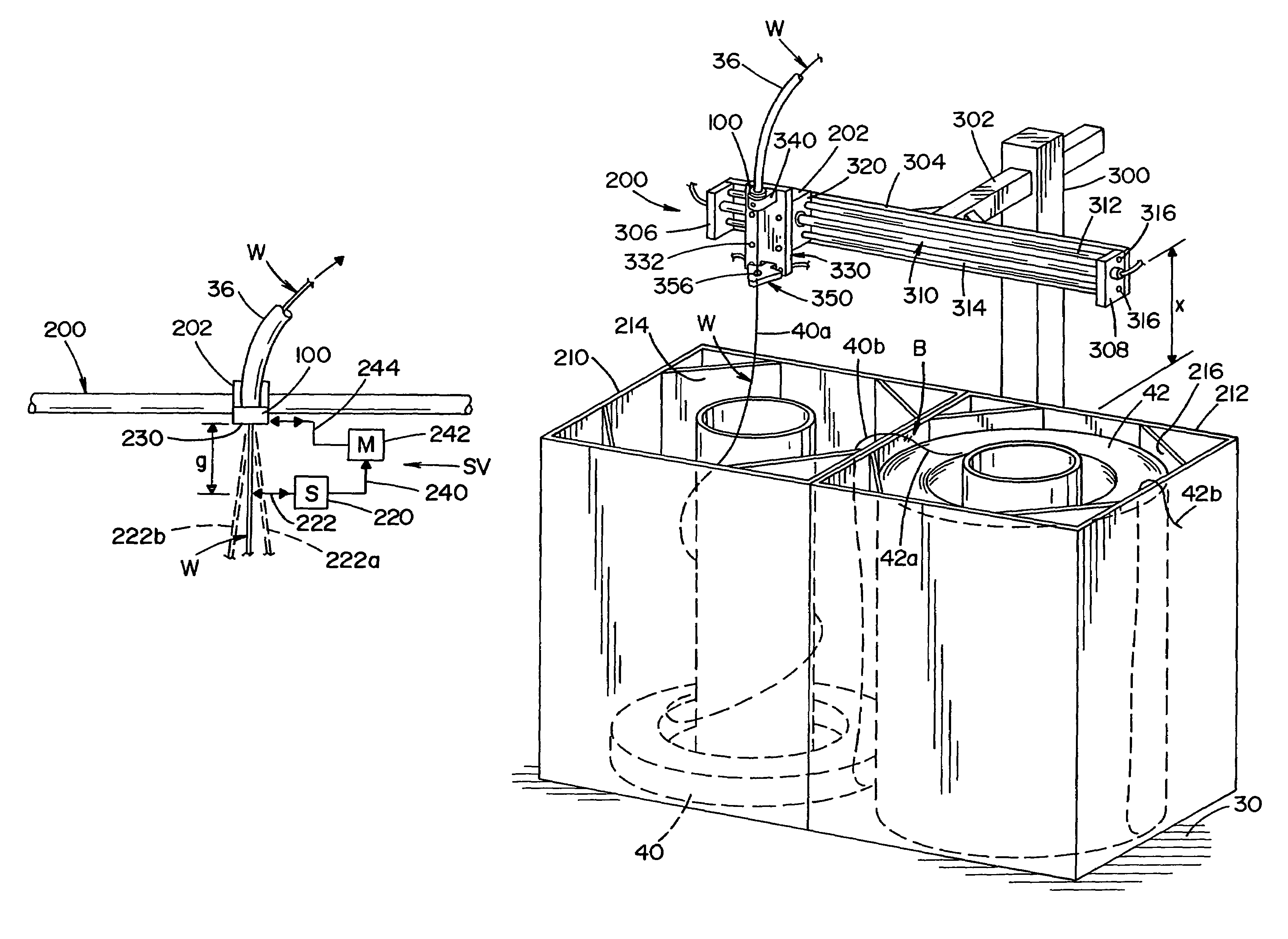
The present invention solves problems associated with prior devices for endless welding wire installations by providing a device for feeding, towards a welding station, welding wire coiled in two separate containers and joined together into an "endless welding wire." The invention reduces the head room necessary for the endless welding wire installation and increases the locations that will accommodate the installation. The invention also includes a track element and a carrier that move the grommet to align with the wire trajectory and a servo mechanism to move the grommet to the desired location. The invention also uses a rodless cylinder and a magnetic coupling to position the guide. Overall, the invention simplifies the process of installing an endless welding wire in an endless welding wire installation.

Problems solved by technology

This technique is well known; however, it is seldom used because of the difficulty in feeding the wire from one coil and then the next coil by a single wire feeding device capable of accommodating wire from one drum and then wire from the next drum.
This creates interference with associated mechanisms and structures adjacent the wire feeder.
In some factories, such clearance is not available, thus, causing rejection of this feeder for an endless welding wire.
Thus, the wire extending from the packages to the grommet exposes high voltage, requiring some type of protective guard around the feeding operation.
Such guard presents another obstacle to using the standard feeding device for endless welding wire.
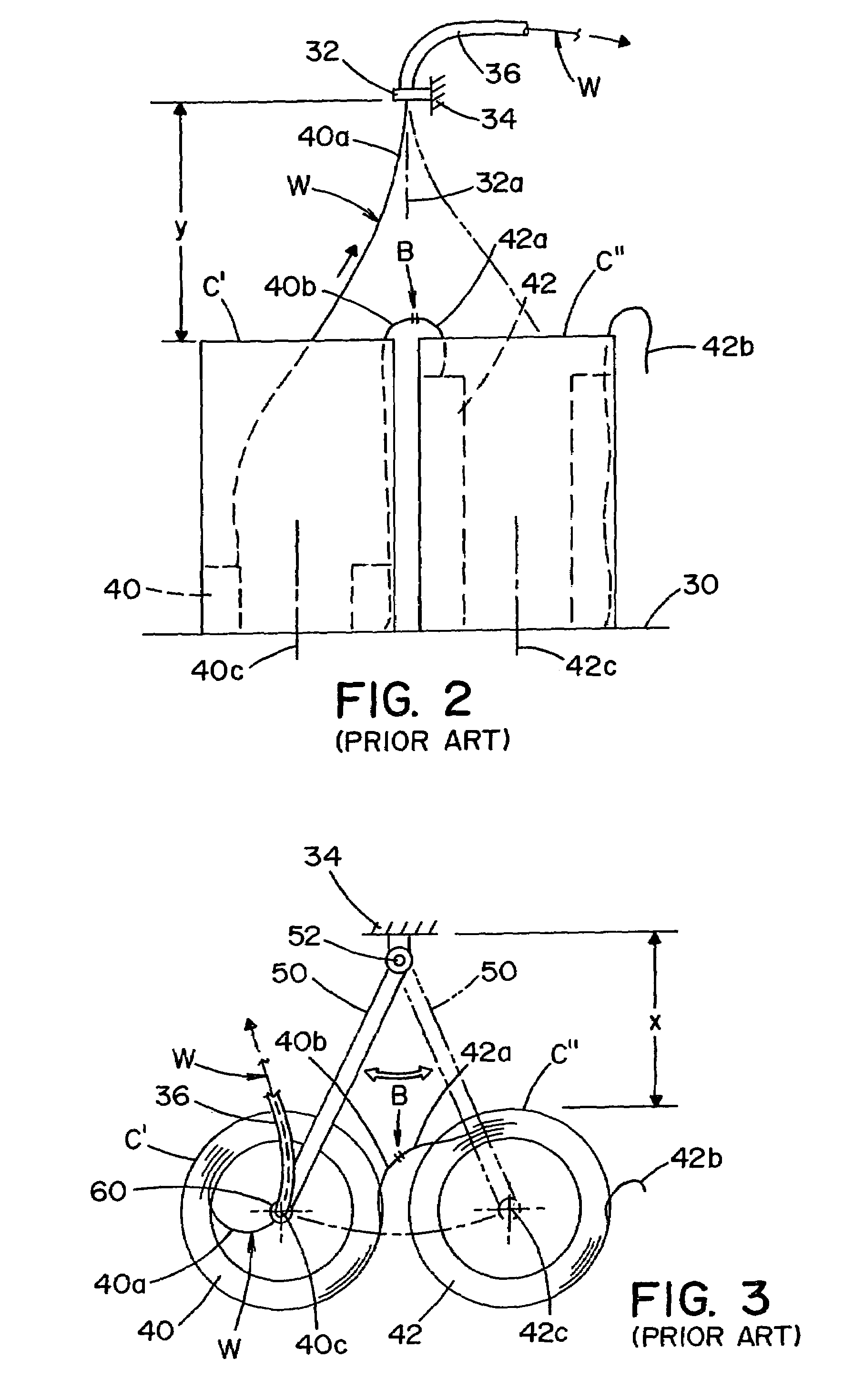
Thus, the vertical height remained a spatial problem.
Furthermore, the pivoting arm, not only caused certain difficulties when shifting from one coil to the next coil, but also maintained a large length of exposed, bare welding wire with open circuit voltage.
They both have the problem of excessive height requiring vertical clearance for the area containing the two welding wire packages and result in a substantial length of exposed wire.
Furthermore, the swinging arm feeding device promotes tanglements, as the arm swung from one coil supply to the next coil supply at changeover.
This upsets the end surfaces and welds the two welding wires together.

Method used


Image

  • Feeder for endless welding wire
  • Feeder for endless welding wire
  • Feeder for endless welding wire

Examples


Embodiment Construction

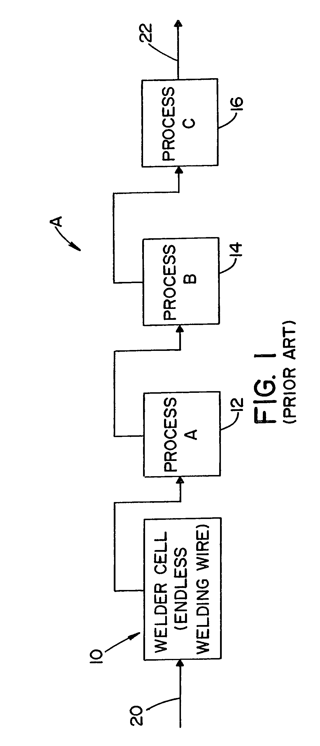
[0039]The present invention relates to a wire feeder for an endless welding wire installation such as installation 10 in production or assembly line A shown in FIG. 1. The welding cell using an endless welding wire is part of several manufacturing operations, indicated generally as processes 12, 14 and 16. A component or part enters at input 20 and is processed successively by the welding cell in series with several distinct processing operations to produce a completed part or assembly 22. This type of assembly line, or production line, is a “just in time” manufacturing system. Consequently, an endless welding wire for welding cell 10 is advantageous so the welding wire is never exhausted; therefore, cell 10 need not be shut down for changing the supply of wire. FIG. 1 illustrates that a shut down to replace an empty supply of welding wire with the next supply of welding wire has the effect of shutting down all of the processes 12, 14 and 16. This interruption of flow drastically af...


PUM

PropertyMeasurementUnit
distanceaaaaaaaaaa
movementaaaaaaaaaa
magneticaaaaaaaaaa

Abstract

A device is provided for feeding an endless welding wire stored in a first container in a first coil generally concentric with a first vertical axis and a second container in a second coil generally concentric with a second vertical axis spaced longitudinally from the first axis in a given direction. The novel device including a track element extending in a path generally including the coil axes and extending above the coils in the given direction. A grommet, with a vertical wire receiving guide opening, is mounted on a support mechanism carried by the track element for movement of the grommet above the coils and along the path of the track element.

Description

[0001]The present invention relates to the art of electric arc welding and more particularly to a feeder device for feeding an endless welding wire to an arc welding station.INCORPORATION BY REFERENCE[0002]The welding wire feeding device of the present invention relates to the concept of using a continuous welding wire from successive drums containing coiled wire with a feed end and a trailing end, both of which ends are exposed from the top of the drum with the trailing end of the coil being fed to the welding station butt welded to the feed end of the next coiled welding wire. This high production technology is becoming quite popular with mass production lines such as used in automobile production. One feeder suggested for commercial application is described in PCT application WO 02 / 094493 where the spaced drums incorporate a wire feeder using an upper guide tube only. This application is incorporated by reference herein as background information regarding the technology to which ...

Claims


Application Information

Patent Timeline
Patent Type & Authority Patents(United States)
IPC IPC(8): B23K9/12B65H23/00B65H26/00B65H57/18
CPCB23K9/1333
Inventor BARTON, DAVID J.CARROSCIA, MICHAEL A.HSU, CHRISTOPHER
Owner LINCOLN GLOBAL INC
Learn More