Cordset based appliance controller

a technology of appliance controller and cordset, applied in the field of electronic control, can solve problems such as luminous discharge, permanent entry of the fuse, and injury or death

Inactive Publication Date: 2007-05-22
X L SYNERGY
View PDF52 Cites 52 Cited by
  • Summary
  • Abstract
  • Description
  • Claims
  • Application Information

AI Technical Summary

Benefits of technology

[0033]d) it can offer protection from electrical ground faults anywhere in the appliance cord, from the plug forward, and anywhere within the load;

Problems solved by technology

Since the human body can conduct the flow of electrical current, if a person comes into contact with one electrified object while simultaneously making contact with a second electrified object having a different voltage, then an electrical leakage current that is proportional to the difference will flow through the person and may cause injury or death.
In electrical appliances, a potential fire hazard can occur when electrical current flows across a leakage path from one electrified conductor to another, resulting in a luminous discharge.
When relatively high currents are passed through a fuse, heating within the fuse causes a fusible element to open, thereby permanently interrupting power flow through the fuse and causing the fuse to permanently enter a second, “open” state.
Then, in the event of an abnormal operating condition, such as a short circuit within the appliance, the high electrical currents that flow through the fuse serve to cause the fuse to go into an open circuit condition or “blow” the fuse, thereby interrupting power.
While a fuse offers some level of protection against heavy currents in an appliance, and consequently offers protection against the electrical fires that can occur when an appliance fails, it does not offer a high level of electrical shock protection to people.
The reason is that electrical currents as low as 5 to 10 milliamperes can be lethal and this level of electrical current is far below the normal operating currents in most electrical appliances.
In the event of a damaged heating element, the load may draw less electrical current but can generate a great deal of heat in the area local to the damage.
This damaged area can lead to fires or burns.
One problem with this approach is that while it protects against a catastrophic failure in the electric blanket, it will not detect or prevent lower level electrical currents that, while insufficient to blow a fuse, are high enough to cause electrical injury or electrocution.
An additional problem with this approach is that it necessitates four conductors connecting between the load (the heater) and the controller.
An additional disadvantage is that the approach requires that the heater load contain positive temperature coefficient (PTC) elements.
An additional disadvantage is that while these designs provide some degree of electrical shock protection at the heating elements, they do not provide protection within the electrical conductors connecting controller to heater or within the electrical conductors connecting plug to controller.
If there is leakage around the load conditioning module (indicating a ground fault or arcing fault) this is indicative of a potentially dangerous electrical condition and the current flow is interrupted at the plug.

Method used


Image

  • Cordset based appliance controller
  • Cordset based appliance controller
  • Cordset based appliance controller

Examples


Embodiment Construction

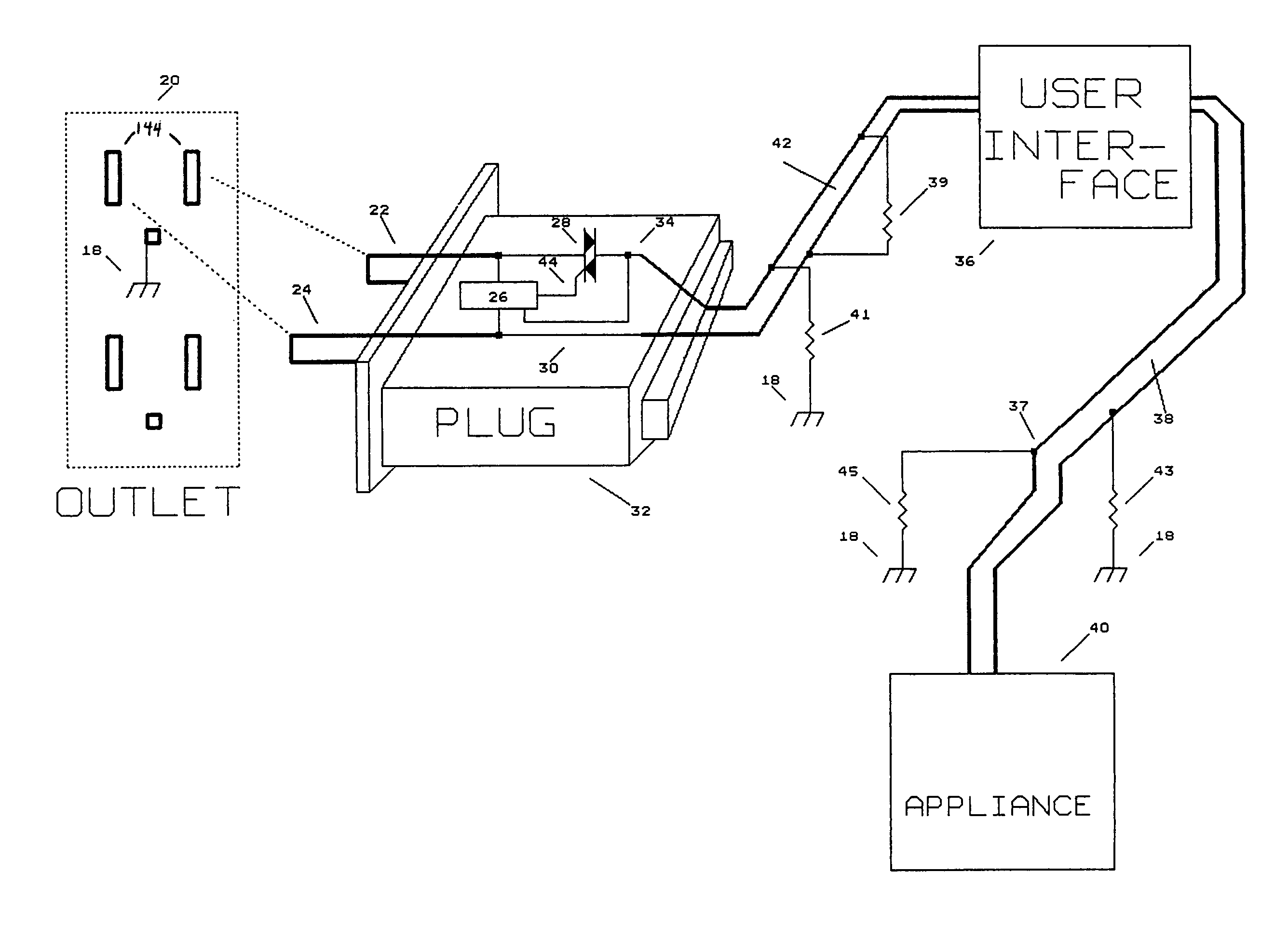
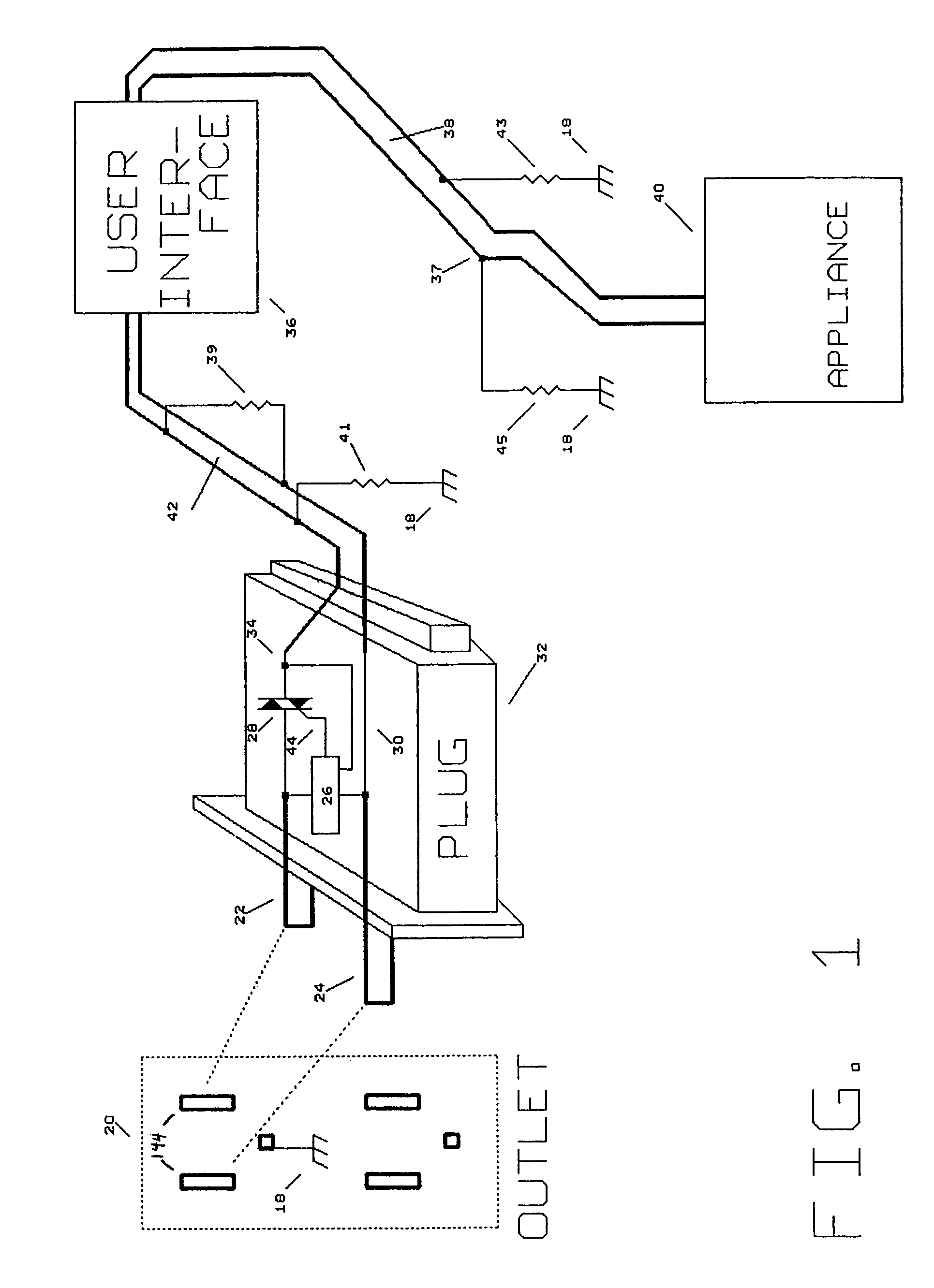
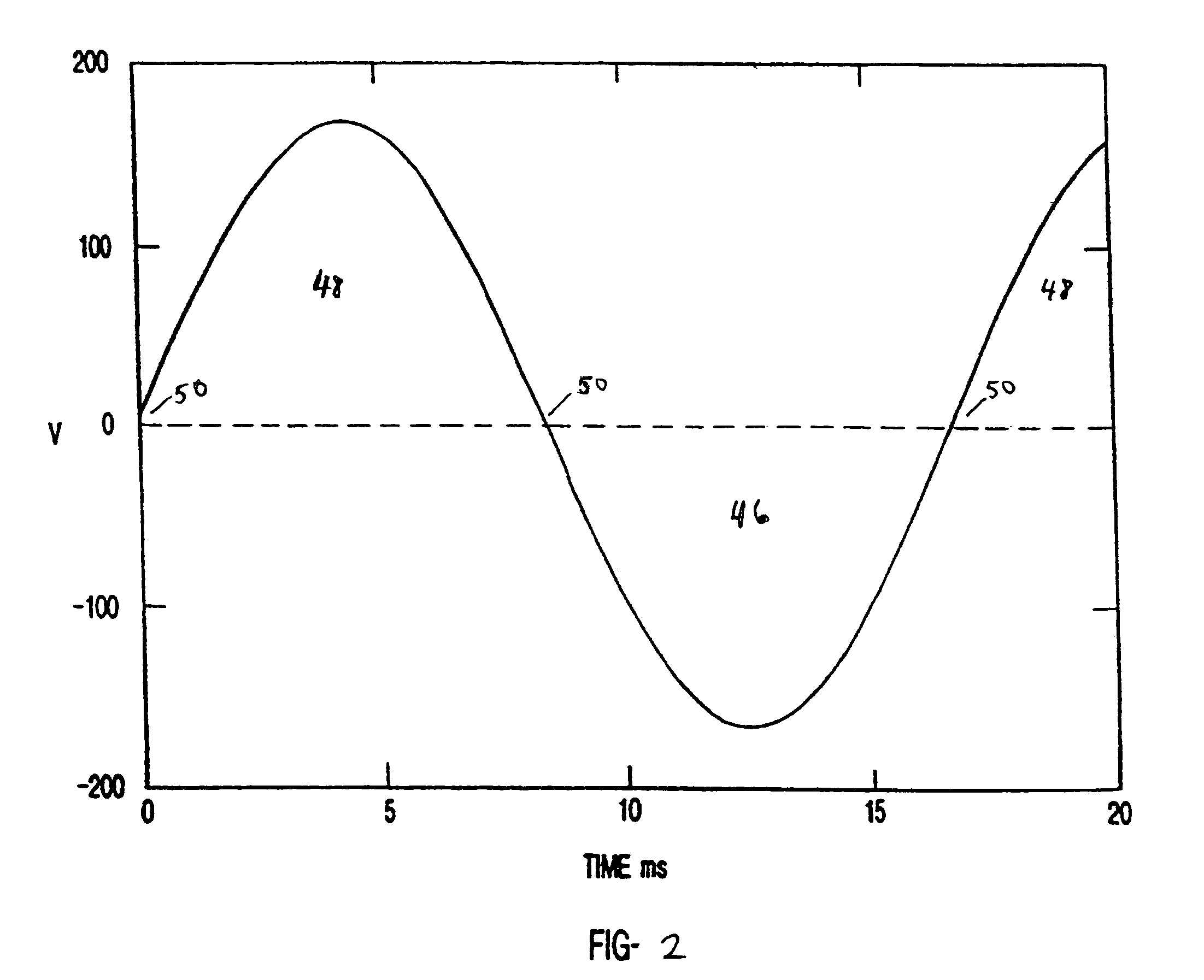
[0134]The present invention is of a method and apparatus for AC appliance control preferably utilizing a minimum of electrical conductors connecting between plug and a user control module and between the user control module and the load. Information is transferred bidirectionally via “deadzones” that are imposed upon the AC load current. In some embodiments, if there is some current flow during a time when a deadzone should occur, this is indicative of a fault condition, either unintentional (as when an undesirable leakage path to ground occurs) or intentional (for example with faults that are deliberately applied using switch closures to impose momentary fault conditions). In other embodiments, by controlling deadzones of AC power to have different lengths, then user inputs, appliance status, and other information may be sent to a remotely located controller or to other locations in the appliance or cordset, without the requirement for additional power conductors. By imposing signa...


PUM


Abstract

An apparatus and method for distributed control of an electrical appliance having a plug and a load and two power carrying conductors connecting the plug to the load, comprising locating power control elements completely within the plug, connecting interface elements to the two power carrying conductors, which interface elements are not within the plug, and transmitting status information from the interface elements to the power control elements by imposition of electrical signals onto the two power carrying conductors, wherein the electrical signals comprise an adjustable duration deadzone at a zero crossing of a sinusoidal excitation.

Description

CROSS-REFERENCE TO RELATED APPLICATIONS[0001]This application is a continuation-in-part application of U.S. patent application Ser. No. 09 / 692,892, entitled “Two-Wire Appliance Power Controller”, to Stanley S. Hirsh, et al., filed on Oct. 19, 2000, issued as U.S. Pat. No. 6,700,333 on Mar. 2, 2004, and the specification thereof is incorporated herein by reference. That application claimed priority to U.S. Provisional Patent Application Ser. No. 60 / 160,275, filed Oct. 19, 1999, and the specification thereof is also incorporated herein by reference.[0002]A related application entitled “Programmable Appliance Controller” is being filed concurrently herewith, to David C. Nemir, et al., Ser. No. 10 / 789,496 and the specification thereof is incorporated herein by reference.STATEMENT REGARDING FEDERALLY SPONSORED RESEARCH OR DEVELOPMENT[0003]Not Applicable.INCORPORATION BY REFERENCE OF MATERIAL SUBMITTED ON A COMPACT DISC[0004]Not Applicable.COPYRIGHTED MATERIAL[0005]Not Applicable.BACKGROU...

Claims


Application Information

Patent Timeline
Patent Type & Authority Patents(United States)
IPC IPC(8): G05F1/00H02M5/257H05B37/02
CPCH02M5/2573H05B37/0209H05B37/0263H02M1/32H02M1/36H02M2001/0012H05B47/10H05B47/185H02M1/0012
Inventor NEMIR, DAVID C.HIRSH, STANLEY S.
Owner X L SYNERGY
Why Eureka
Try Eureka