System and method for operating a loop detector

a loop detector and loop detector technology, applied in the direction of traffic signal control, traffic detection, instruments, etc., can solve the problems of loop detectors being ignored, detection thresholds become unreliable and must be changed, and average filter approaches have proved inadequate to compensate for long range changes

Inactive Publication Date: 2007-05-22
THE CHAMBERLAIN GRP INC
View PDF6 Cites 26 Cited by
  • Summary
  • Abstract
  • Description
  • Claims
  • Application Information

AI Technical Summary

Benefits of technology

[0011]Thus, approaches are provided to maintain an updated detection threshold in a system using a loop detector to actuate a moveable barrier. The approaches described herein avoid the problems associated with previous systems such as missed detections of vehicles in the loop and premature barrier closings of vehicles entering through the barrier.

Problems solved by technology

Consequently, the detection threshold becomes unreliable and must be changed if accurate responses to loop inductances are to be made.
However, the running average filter approach has proven inadequate to compensate for long range changes in system operation.
For instance, the running averages approach often causes the loop detector to ignore a vehicle when the vehicle was on the loop for a long period of time or when a number of vehicles traversed the loop sequentially.
Consequently, the gate might never be opened to allow a waiting vehicle to pass through the gate.
In other circumstances, the gate might close prematurely damaging one of the string of vehicles passing through the gate.

Method used


Image

  • System and method for operating a loop detector
  • System and method for operating a loop detector
  • System and method for operating a loop detector

Examples


Embodiment Construction

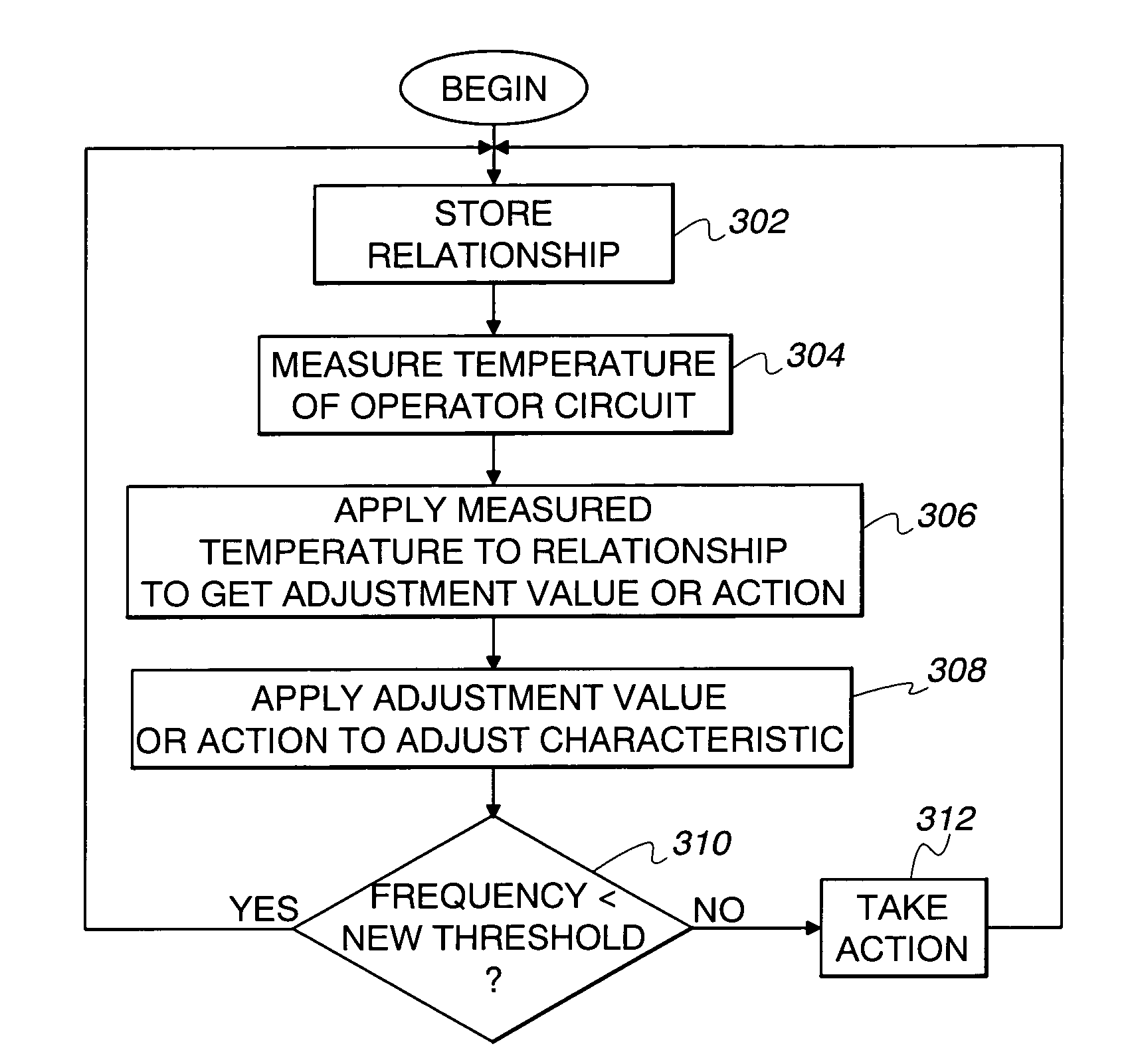
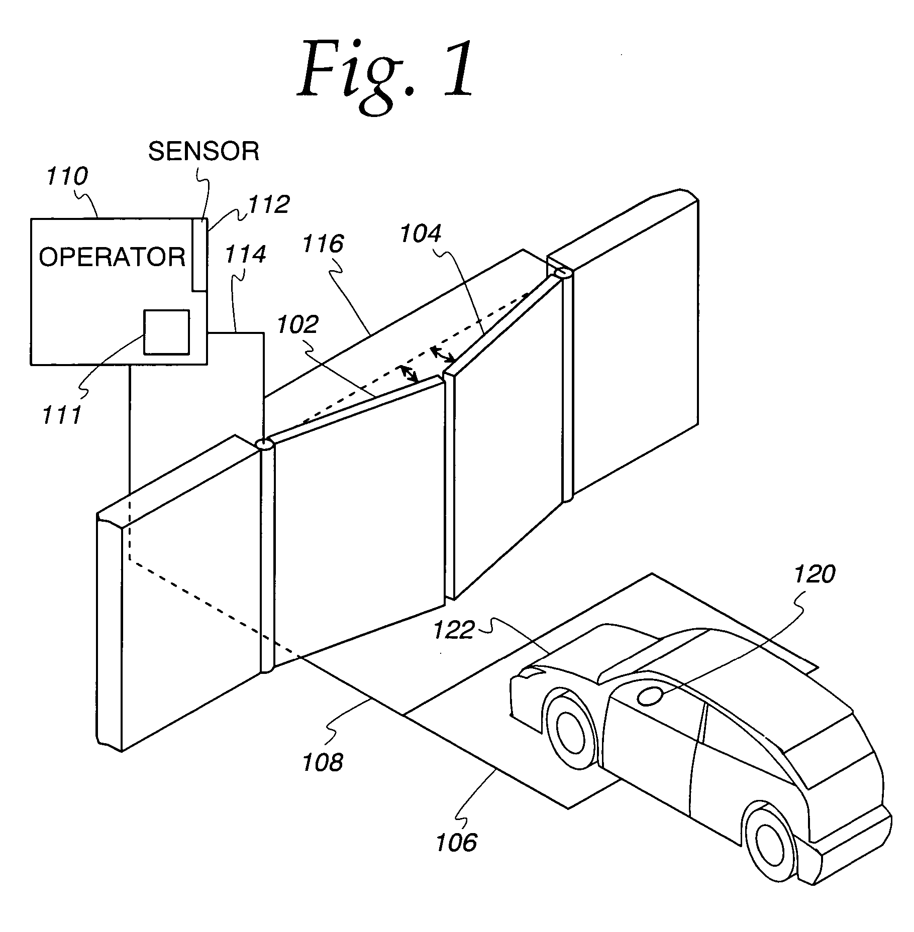
[0017]Referring now to the drawings and especially FIG. 1, a system using a loop detector to open and close a moveable barrier is described. A wire loop 106 is placed in the ground in front of gates 102 and 104. The loop 106 is coupled to an operator 110 via a cable 108. The cable 108 provides a path for electrical signals representative of the inductance of the loop 106.

[0018]For illustrative purposes, the description with respect to FIG. 1 refers to moveable barriers that are gates. However, it will be understood by those skilled in the art that the moveable barrier may not only be a gate, but may be any type of barrier such as a fire door, shutter, window, garage door. Other examples of barriers are possible.

[0019]The operator 110 may provide circuitry for driving the loop detector 106 with an oscillator 111. For convenience in viewing, the operator 110 is shown placed above a wall. However, it will be understood that the operator 110 may be positioned in any convenient and / or se...


PUM


Abstract

The temperature of an operator circuit is measured. A relationship between the temperature of the operator circuit and characteristics of the operator circuit is determined. The relationship is applied to the measured temperature of the operator circuit to create an adjustment action. The detection threshold is adjusted by the adjustment action.

Description

FIELD OF THE INVENTION[0001]The field of the invention generally relates to methods and devices for controlling loop detectors. More specifically, the invention relates to adjusting the characteristics of loop detectors over time.BACKGROUND OF THE INVENTION[0002]Loop detectors function by having a circuit detect the change in inductance of a wire loop when a vehicle enters the vicinity of the loop. For instance, in some previous systems, the loop inductance changes by approximately four percent when a vehicle enters the loop. This change of inductance may be detected by sampling the change of frequency of electrical signals used to oscillate the loop.[0003]Loop detectors are frequently used at traffic lights to indicate that a vehicle is present at an intersection and to initiate the changing of the light so that the vehicle can proceed through the intersection. In another example, loop detectors are sometimes placed in front of a barrier, such as a gate or a garage door. When a veh...

Claims


Application Information

Patent Timeline
Patent Type & Authority Patents(United States)
IPC IPC(8): G08G1/01
CPCG08G1/042
Inventor HOM, WAYNE C.
Owner THE CHAMBERLAIN GRP INC
Why Eureka
Try Eureka