Eureka AIR delivers breakthrough ideas for toughest innovation challenges, trusted by R&D personnel around the world.

Electromagnetic inclinometer

a technology of inclinometer and inclinometer, which is applied in the field of inclinometer, can solve the problems of complex and unsuitable for many applications, slow recovery from shocks, and simple and rugged, and achieve the effect of simple and rugged, and avoiding the problems inherent in electrolytic sensors

Inactive Publication Date: 2007-05-29
AUTONNIC RES
View PDF16 Cites 3 Cited by
  • Summary
  • Abstract
  • Description
  • Claims
  • Application Information

AI Technical Summary

Benefits of technology

[0011]The present invention seeks to provide an electromagnetic inclinometer that is both simple and rugged and yet avoids the problems inherent in electrolytic sensors.
[0017]Preferably, the device may be constructed inside a box adapted to eliminate the earth's field.
[0018]The use of floating cores is known from other applications such as flux gate compasses (see U.S. Pat. No. 5,282,318 for example), in which the core floats so that it remains horizontal, thereby ensuring that only the horizontal component of the Earth's magnetic field is measured. By floating the core the voltage induced in the sense windings are the same regardless of the inclination of the compass device, thereby eliminating tilt. However, in the invention, the horizontal component of the Earth's magnetic field is eliminated in favour of a field fixed with respect to the housing.

Problems solved by technology

This arrangement is very robust being adapted to work at oil well formation temperatures but is inevitably quite complex and unsuitable for many applications.
These devices haven proven in the field to be simple and rugged but suffer a number of drawbacks.
In particular, they can be slow to recover from shocks as the fluid will be shaken up and give false readings due to the presence of air bubbles and there is tendency for the electrolyte to lose conductivity over time due to electrolysis.

Method used


Image

  • Electromagnetic inclinometer
  • Electromagnetic inclinometer
  • Electromagnetic inclinometer

Examples


Embodiment Construction

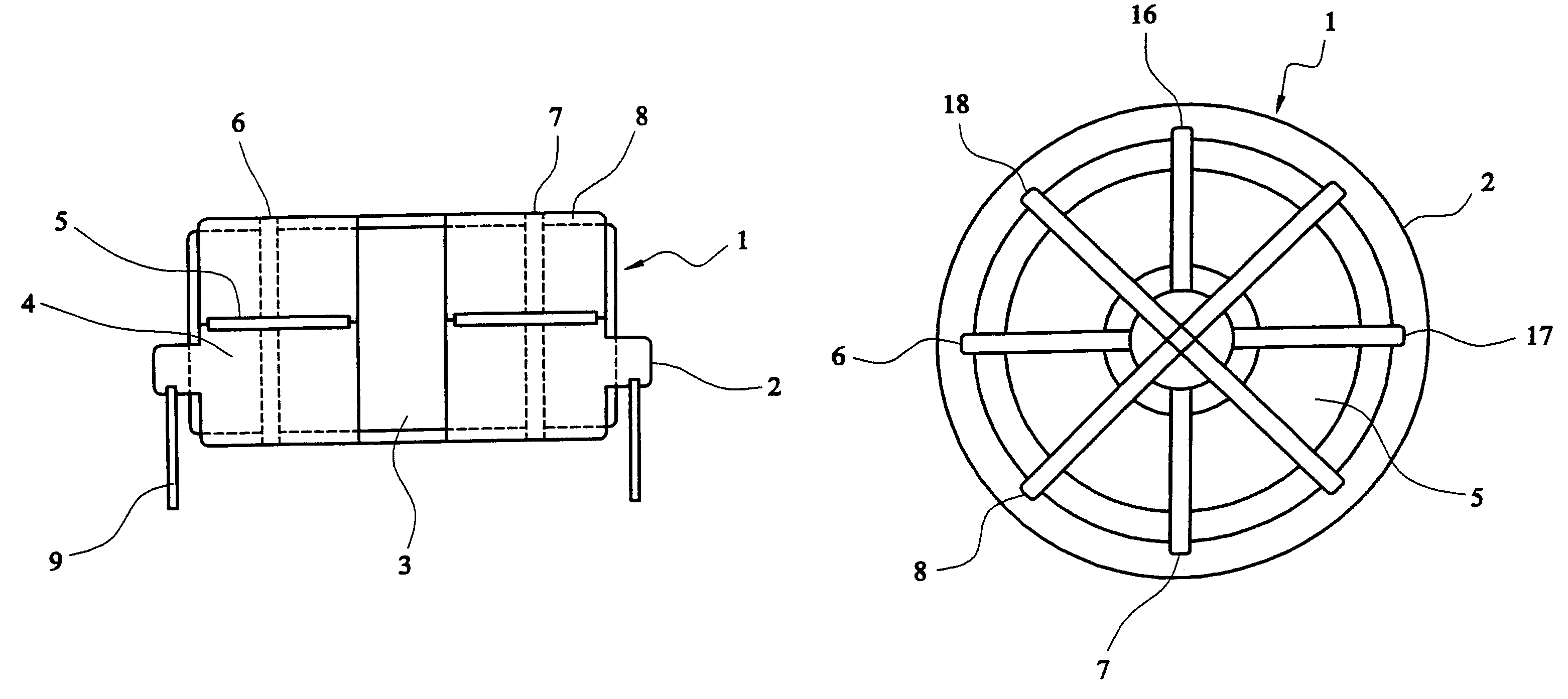
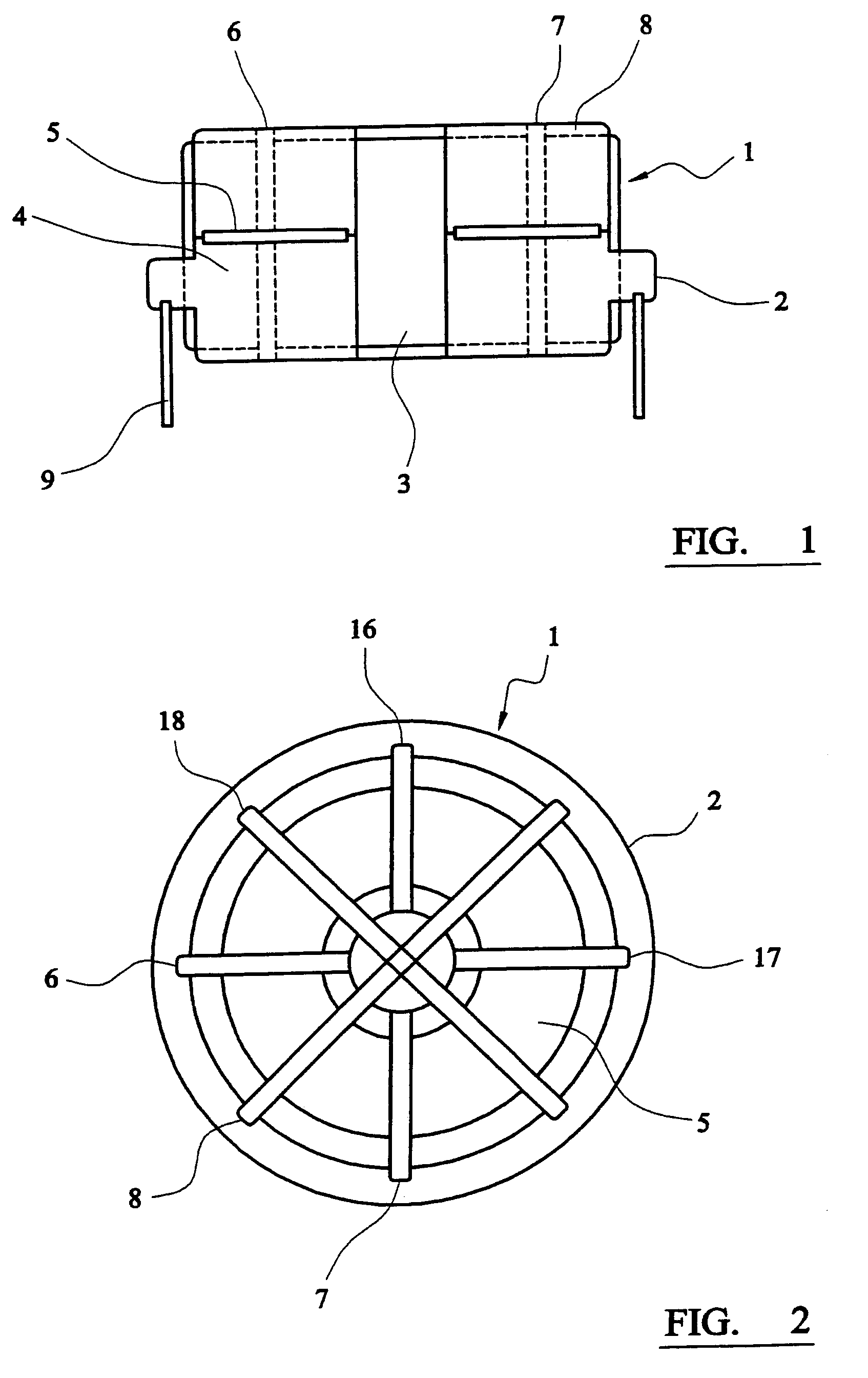
[0024]FIG. 1 shows a cross section of an inclinometer comprising a substantially cylindrical annular housing 1 having an annular flange 2 situated towards the lower portion of the housing 1. The housing 1 has a central opening 3 and grooves in the surface of the housing adapted to receive windings.

[0025]The housing 1 is about half full with a liquid 4. A magnetic core 5, is attached to a float, the core also having an annular form, so that the core floats on the liquid. The magnetic core 5 is keyed to substantially prevent any rotation in the housing 1.

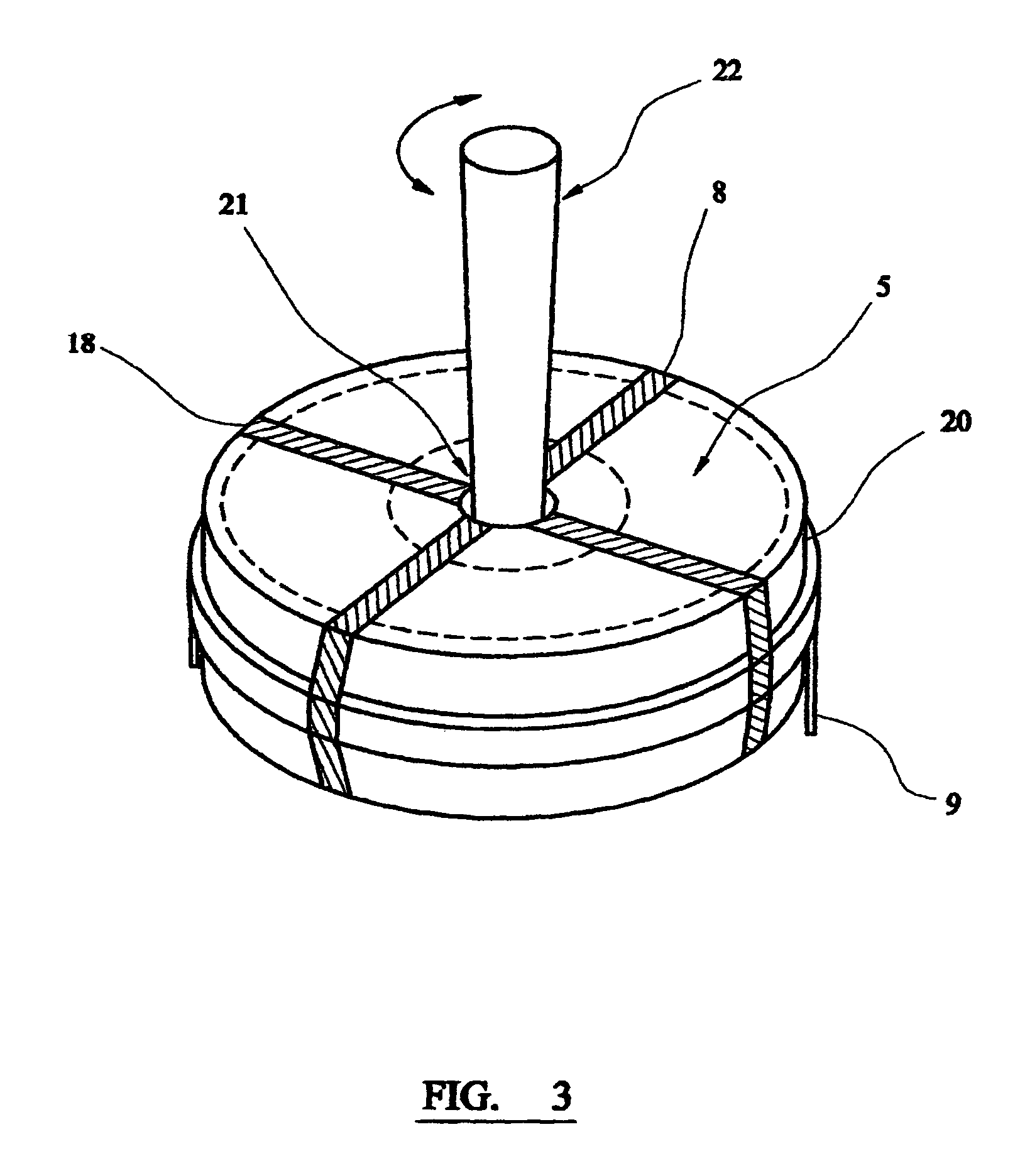
[0026]Toroidal windings 6,7 are shown in dashed lines, which are wrapped around the housing and hence the core passing through the annular opening in the housing 1. A further sense winding 8 is provided which is wrapped around the housing 1 but does not pass through the annular opening.

[0027]The flange 2 is provided with mounting points for a plurality of pins 9, wherein the sense winding 8 is connected to a pin 9 to provide the elect...


PUM


Abstract

An angle sensor comprising a housing (1) having horizontal and vertical axes, which housing is adapted to receive a magnetic core (5) such that the core remains in substantially the same plane, e.g. by floating on a liquid (4). The core is provided with two orthogonal windings (8,18). In use, an electric field is applied across the vertical axis of the housing, which electric field induces a voltage in the windings, wherein the magnitude of the induced field is dependent on the angle of the magnetic core to the horizontal winding.

Description

CROSS-REFERENCES TO RELATED APPLICATIONS[0001]This application is a U.S. National Stage application filed pursuant to 35 U.S.C. §371. Pursuant to the cited section and the Patent Cooperation Treaty, priority is claimed to International Application No. PCT / GB 03 / 00302 having a priority date of Jan. 23, 2002.STATEMENT REGARDING FEDERALLY SPONSORED RESEARCH OR DEVELOPMENT[0002]Not applicable.MICROFICHE APPENDIX[0003]Not applicable.BACKGROUND OF THE INVENTION[0004]1. Background—Field of the Invention[0005]The invention relates to an electromagnetic inclinometer and a method for measuring inclination using said inclinometer.[0006]2. Background—Prior Art[0007]There are many types of inclinometer available on the market for use in a wide variety of applications such as aircraft, geodetic engineering and general land surveying.[0008]U.S. Pat. No. 4,15,7619 discloses an inclinometer for use in measuring water flow rates comprising a coil energised to produce a magnetic field extending along ...

Claims


Application Information

Patent Timeline
Patent Type & Authority Patents(United States)
IPC IPC(8): G01C9/20G01C9/06
CPCG01C9/06G01C2009/064
Inventor SHELTON, CHRISTOPHER
Owner AUTONNIC RES
Why Eureka
Eureka Blog
Learn More