Gripping pliers

a technology of gripping pliers and pliers, which is applied in the field of gripping pliers, can solve the problems of limited detent position possible minimum spacing, and achieve the effect of reducing friction and fine adjustment of opening width

Inactive Publication Date: 2007-05-29
EDUARD WILLE GMBH & CO KG
View PDF10 Cites 18 Cited by
  • Summary
  • Abstract
  • Description
  • Claims
  • Application Information

AI Technical Summary

Benefits of technology

[0005]It is an object of the invention to improve the bearing structure of the joint in pairs of gripping pliers of this type. It is another object of the invention, to permit fine adjustment of the opening width of the pair of gripping pliers.
[0008]In this way, the joint, on one hand, is ruggedly supported in detent positions provided on both sides of the central second leg. On the other hand, a fine adjustment in accordance with the tooth spacing of the toothed edges is possible. Preferably said toothed edges comprise teeth and tooth gaps of substantially triangular shape, and said detent lugs are substantially roof-shaped projections of said detent body. This permits very fine adjustment of the opening width of the gripping pliers.
[0009]It is advantageous, if detent lugs of said detent body partly engage said radial recesses of said profiled bearing ring also in said second axial position of said detent body. Thereby, the relative orientation of the profiled bearing ring with respect to the detent lugs is ensured, such that movement of the detent body from its first axial position to its second axial position is always possible.
[0010]The pair of pliers may further comprise resilient means for biasing said detent body towards said second axial position, said resilient means being supported by said profiled bearing ring. In order to reduce friction, when shifting the joint, said profiled bearing ring may have a stepped peripheral surface and may be mounted in a correspondingly stepped bore of said handle such as to maintaining an end face of said profiled bearing ring remote from said resilient means spaced from the neighboring one of said inner surfaces of said longitudinal slot.

Problems solved by technology

These bores, however, have to have a certain size, whereby the possible minimum spacing of the detent positions is limited.

Method used


Image

  • Gripping pliers
  • Gripping pliers
  • Gripping pliers

Examples


Embodiment Construction

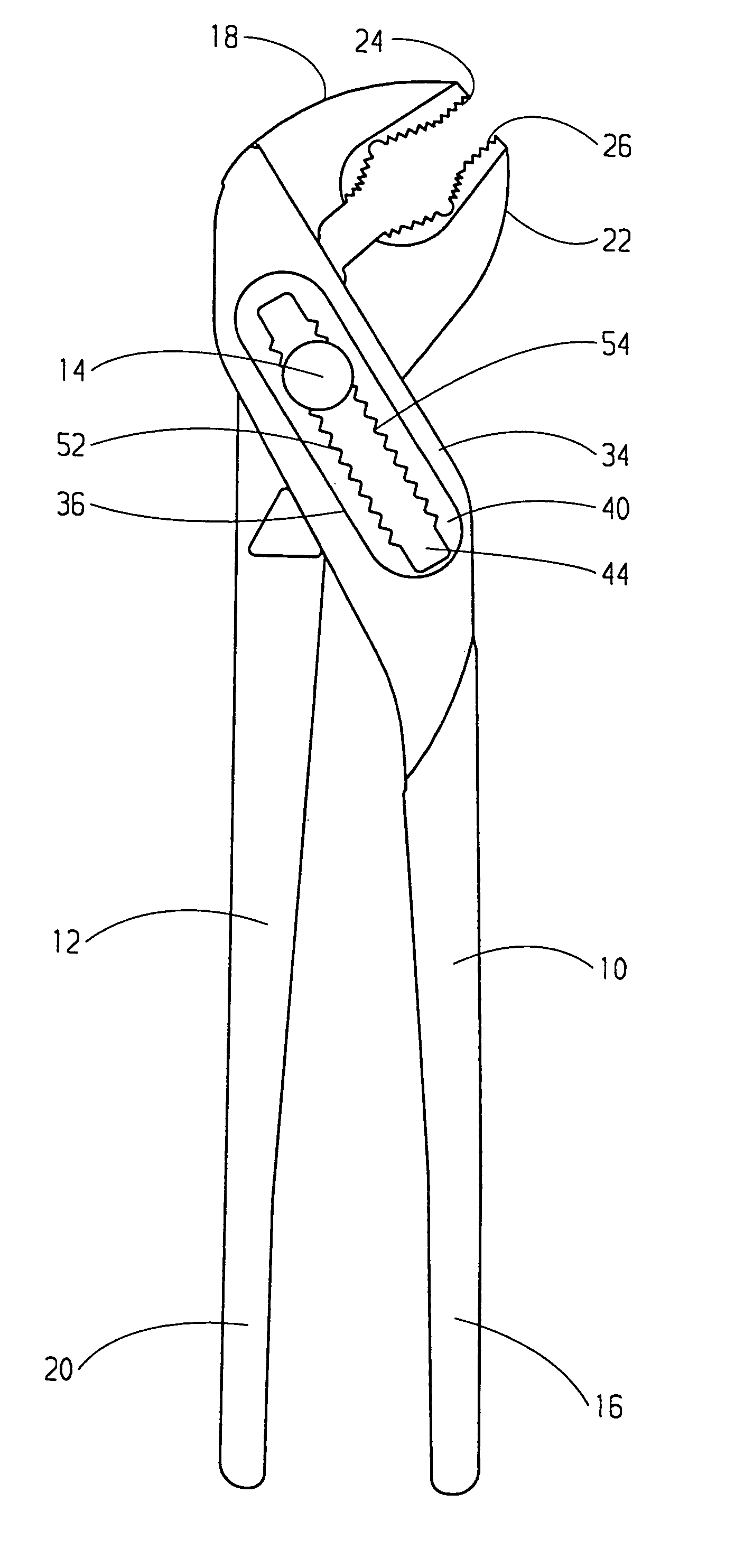
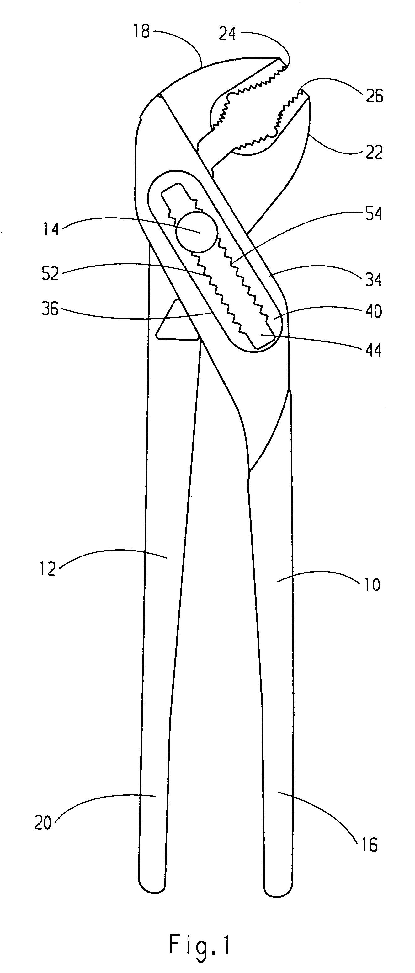
[0025]FIGS. 1 and 2 show a pair of gripping pliers viewed from opposite sides. In the art, such a pair of gripping pliers is termed “water pump pliers”. The gripping pliers has a first leg or “clamp”10 and a second leg or “handle”12. Clamp and handle are articulated by means of a joint 14. The clamp 10 has a handle portion 16 and a pliers yaw 18. The handle 12 has a handle portion 20 and a pliers yaw 22. The pliers yaws 18 and 22 are angled relative to the handle portions 16 and 20, respectively, such that their gripping surfaces 24 and 26, respectively, facing each other are substantially parallel, when the pair of gripping pliers is in its closing or gripping position. Each of the gripping surfaces forms a recess toothed in conventional manner to permit holding of a tube or the like between the gripping surfaces.

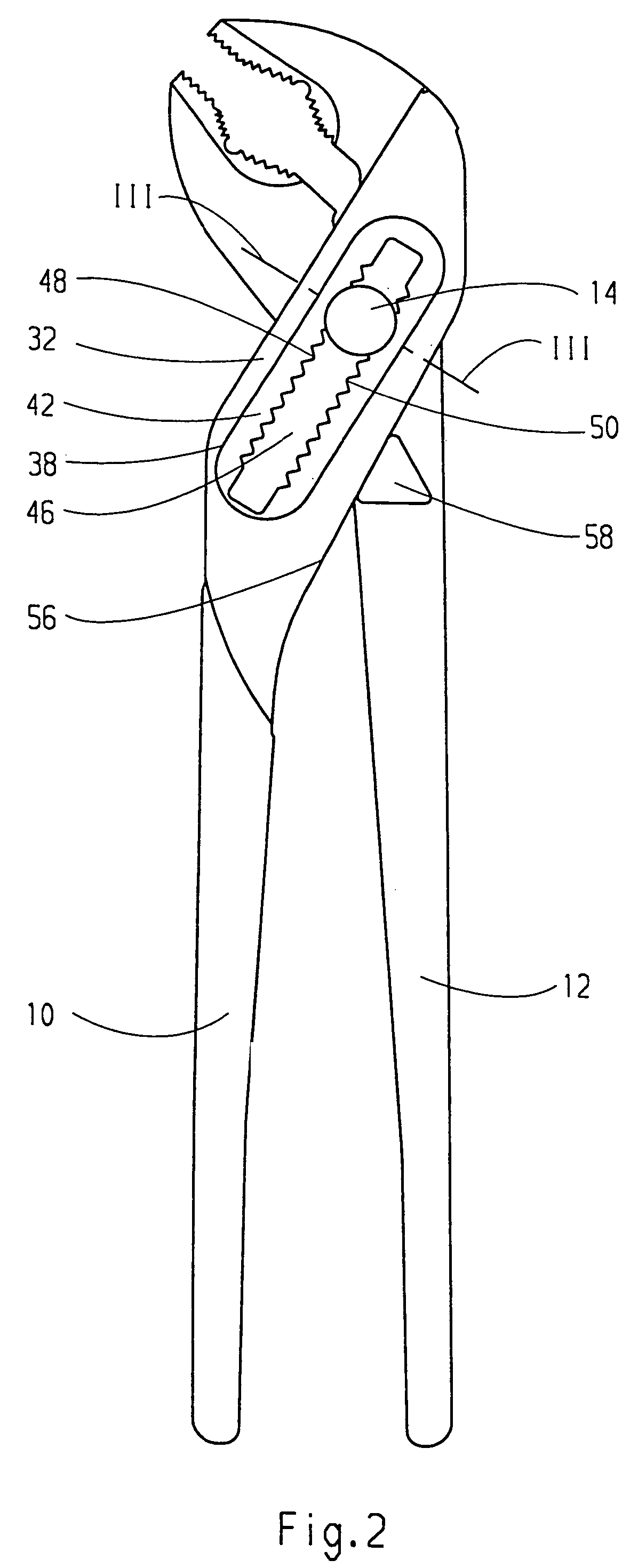
[0026]In the region of the joint 14, the clamp 10 has a slot 28 (FIG. 3 or 3A) extending through the clamp 10, the plane of this slot extending normal to the axis of rotat...


PUM


Abstract

Gripping pliers consisting of a jointed clamp and handle. The clamp contains a longitudinal slot with longitudinal apertures defining first and second detent positions. In the first position, the joint is movable whereas in the second position, the joint is locked. The handle is rotatably mounted on a bearing ring which permits fine adjustment of the opening width of the pliers.

Description

BACKGROUND OF THE INVENTION[0001]The invention relates to a pair of gripping pliers, generally called “water pump pliers”. A pair of water pump pliers is generally understood to be a pair of pliers with a first and a second leg (“clamp” and “handle”), each of which have a handle portion and a pliers yaw and which are interconnected between the handle portions and the pliers yaws by means of a joint. The joint is guided in a longitudinal aperture of the first leg, this aperture being provided with detents. By adjusting the joint in the longitudinal aperture, the opening width of the pliers, i.e. the spacing of the pliers yaws, can be varied with substantially parallel gripping surfaces. By such an arrangement, it is possible to adapt the opening width to the dimensions of the part to be gripped and to grasp parts of considerably different diameters in the same way. A flat section with a longitudinal slot is provided at the clamp, the handle extending through this longitudinal slot. P...

Claims


Application Information

Patent Timeline
Patent Type & Authority Patents(United States)
IPC IPC(8): B25B7/04B25B23/16B25B7/06E05D15/06F16C11/00F16D1/12F16D3/00B25B7/10
CPCB25B7/10Y10T16/5448Y10T403/32344
Inventor SCHMITT, LOTHARCHNIEL, HANS-JOACHIM
Owner EDUARD WILLE GMBH & CO KG
Why Eureka
Try Eureka