

Dual-mass flywheel
- Summary
- Abstract
- Description
- Claims
- Application Information
AI Technical Summary
Benefits of technology
Problems solved by technology
Method used
Image

Examples
first embodiment
[0030] First Embodiment
[0031] Overall Structure
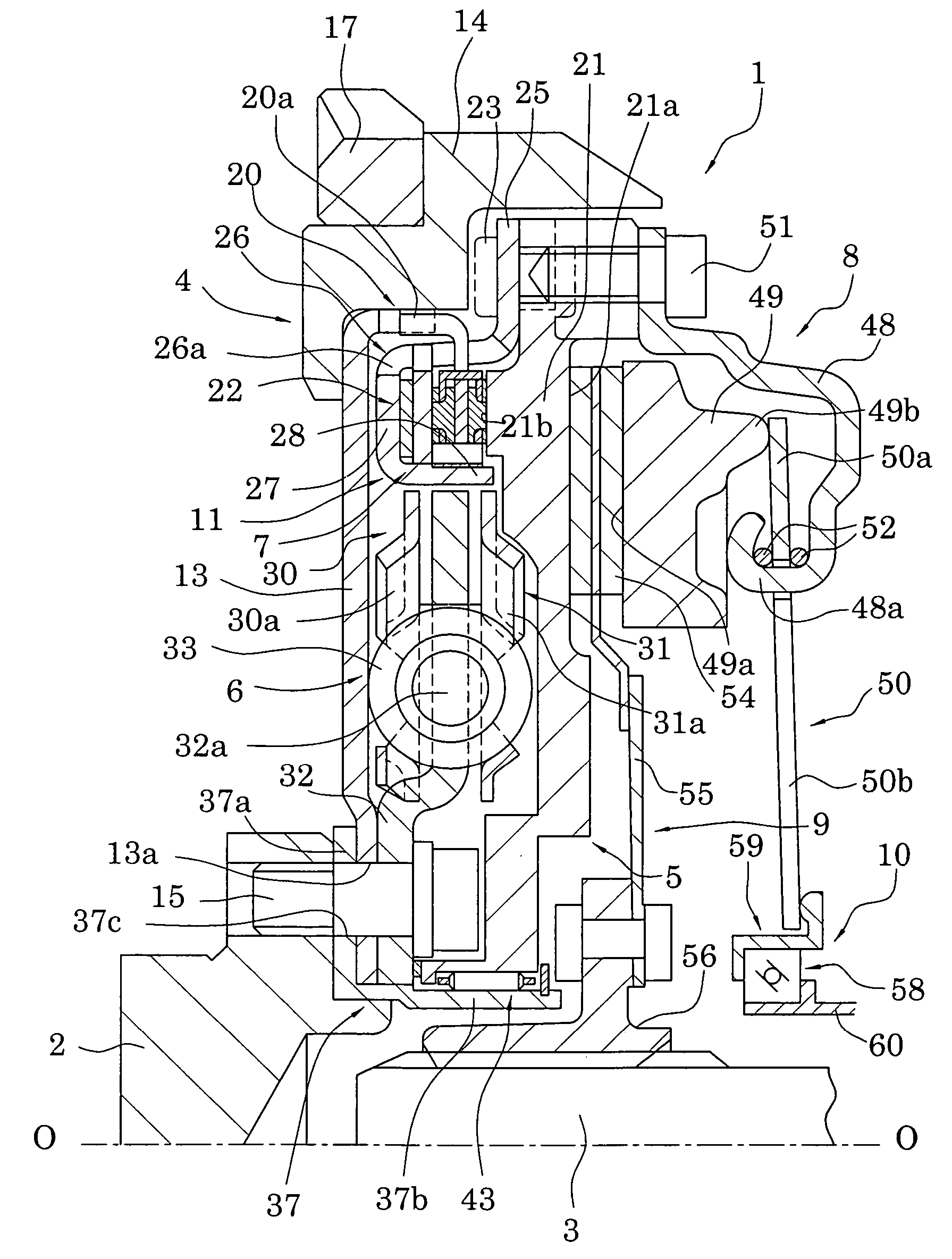
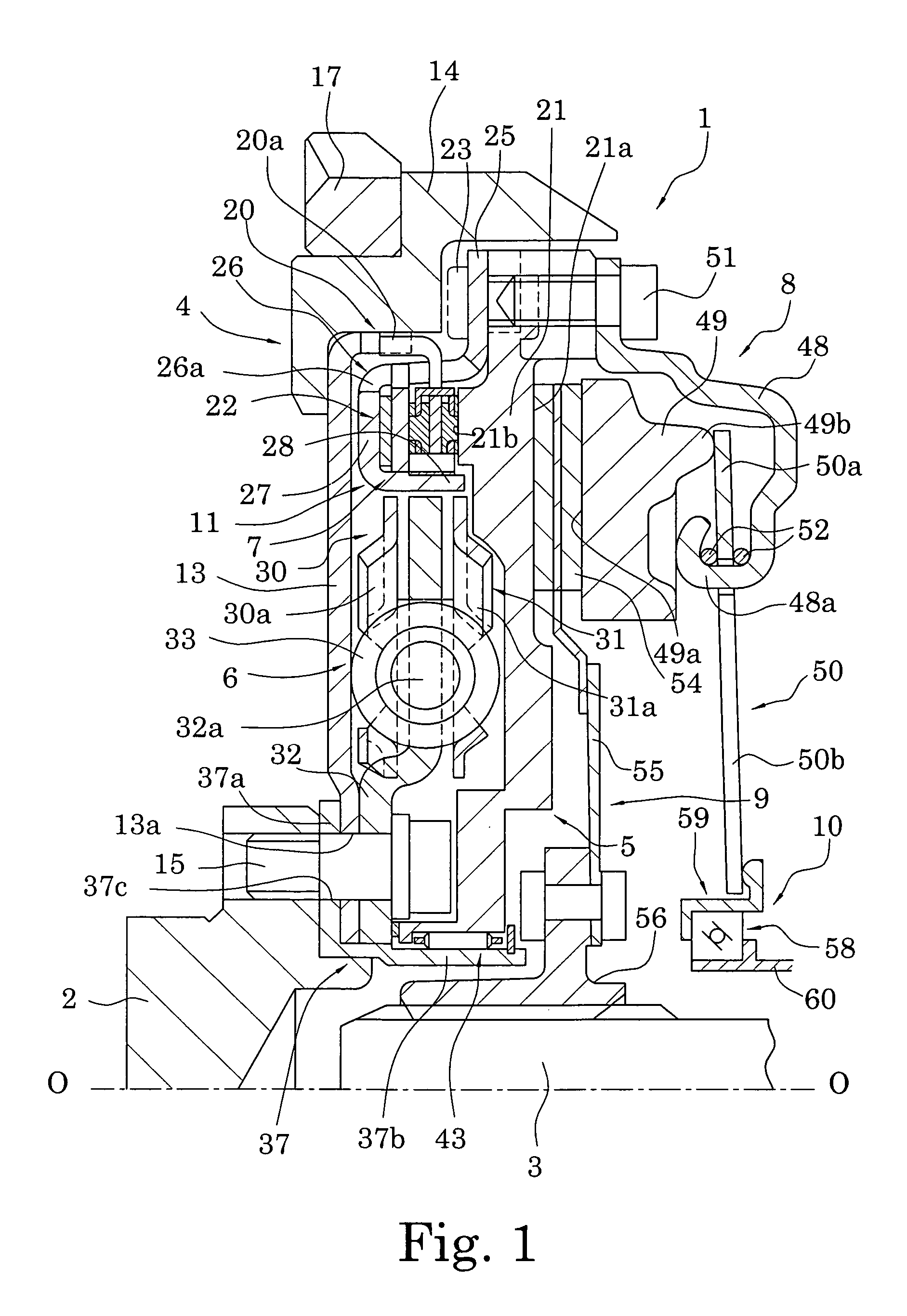
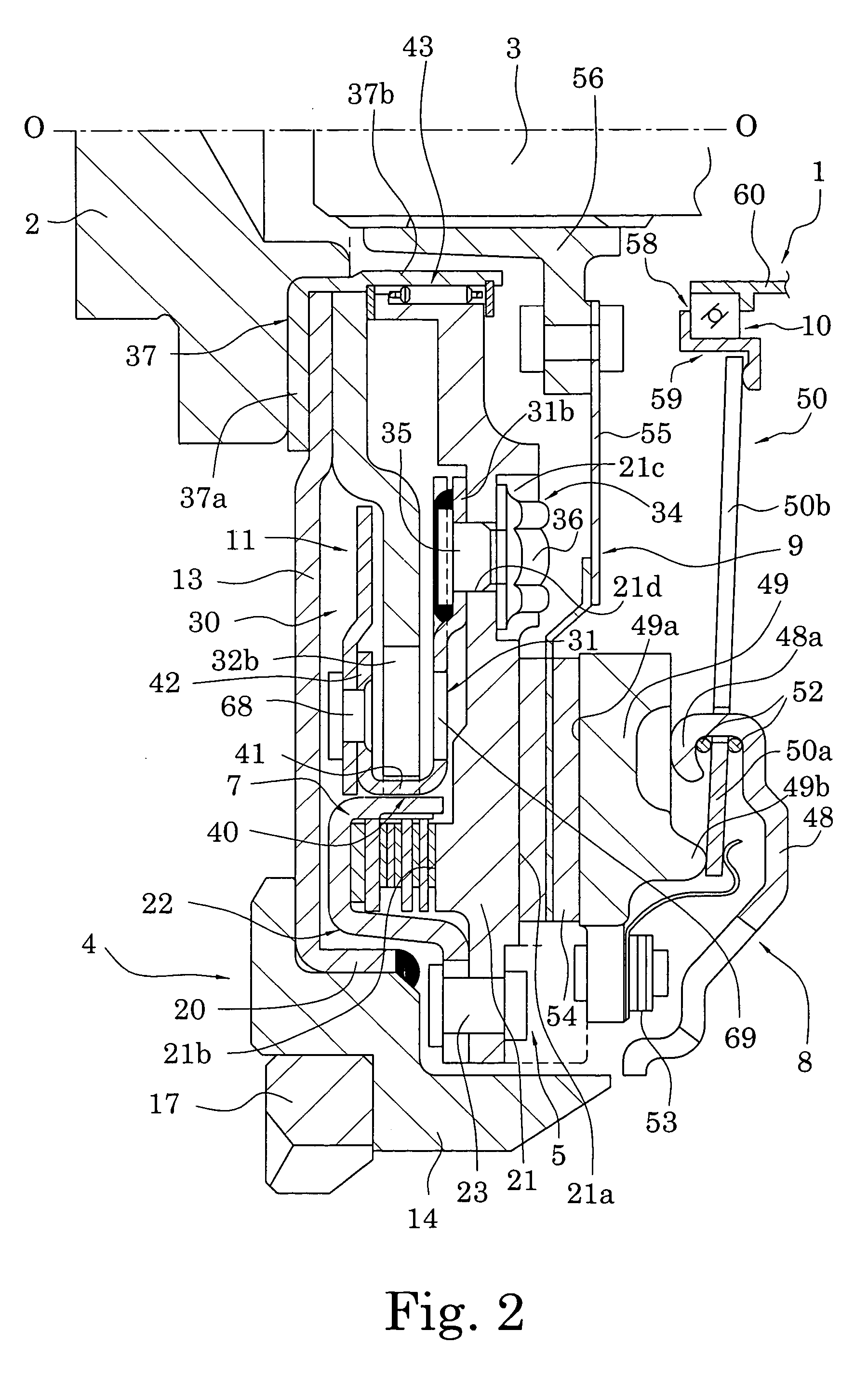
[0032] As shown in FIGS. 1 through 3, a clutch device 1 in accordance with a preferred embodiment of the present invention is configured to transmit and to interrupt torque between a crankshaft 2 on an engine side and an input shaft 3 on a transmission side. The clutch device 1 is primarily formed of a first flywheel assembly 4, a second flywheel assembly 5, a clutch cover assembly 8, a clutch disk assembly 9, and a release device 10. The first and second flywheel assemblies 4 and 5 are combined to form a flywheel damper 11, which includes a damper mechanism 6 and is described later.
[0033] In FIGS. 1 and 2, O-O indicates a rotation axis of the clutch device 1. An engine (not shown) is disposed on the left side in FIGS. 1 and 2, and a transmission (not shown) is disposed on the right side. In following description, the left side in FIGS. 1 and 2 will be referred to as the engine side, which is based on the axial direction, and the righ...
PUM
 Abstract
Description
Claims
Application Information