Unlubricated bearing structure and IC socket using same

a technology of unlubricated bearings and ic sockets, applied in sliding contact bearings, coupling device connections, instruments, etc., can solve problems such as significant achieve smooth operation, reduce wear of support shafts, and improve unlubricated bearings

Active Publication Date: 2013-07-02
ENPLAS CORP
View PDF13 Cites 0 Cited by
  • Summary
  • Abstract
  • Description
  • Claims
  • Application Information

AI Technical Summary

Benefits of technology

[0009]The present invention was conceived in consideration of the above circumstances to solve the defects encountered in the conventional unlubricated bearing structure mentioned above and an object thereof is to provide an unlubricated bearing structure capable of effectively reducing wearing of a support shaft of the unlubricated bearing structure and providing smooth operation of a rocking arm thereof, and also provide an IC package equipped with such an improved unlubricated bearing structure.
[0012]According to the above aspect of the embodiment of the present invention, according to the rocking (swinging) motion of the rocking arm, sliding motions are caused between the outer peripheral surface of the support shaft and the inner peripheral surface of the bush, and also, between the outer peripheral surface of the bush and the inner peripheral surface of the bearing hole, thereby reducing wearing at the sliding contacting portion between the support shaft and the bush, and accordingly, the rocking arm in the present embodiment can be smoothly operated for a long period.
[0015]According to such IC socket provided with the improved unlubricated bearing structure, the IC socket can be smoothly operated for a long period.

Problems solved by technology

However, such unlubricated bearing structure 100 has provided the following defects.
With the conventional bearing structure 100 shown in FIG. 10A and FIG. 10B, when a force F1 other than self-weight pressing the rocking arm 106 toward the center of rocking motion acts, the support shaft 104 made of metal (stainless steel) slidably contacts the cylindrical bush 101, also made of metal (stainless steel), which results in causing of problem of significant wearing of the support shaft 104 as represented by oblique lines in FIG. 10B and the rocking arm is hence hardly driven or operated smoothly and easily, thus being defective and disadvantageous.

Method used


Image

  • Unlubricated bearing structure and IC socket using same
  • Unlubricated bearing structure and IC socket using same
  • Unlubricated bearing structure and IC socket using same

Examples


Embodiment Construction

[0028]A preferred embodiment of the present invention will be described hereunder with reference to the accompanying drawings.

[0029](Electrical Testing Device to which Unlubricated Bearing Structure is Applied)

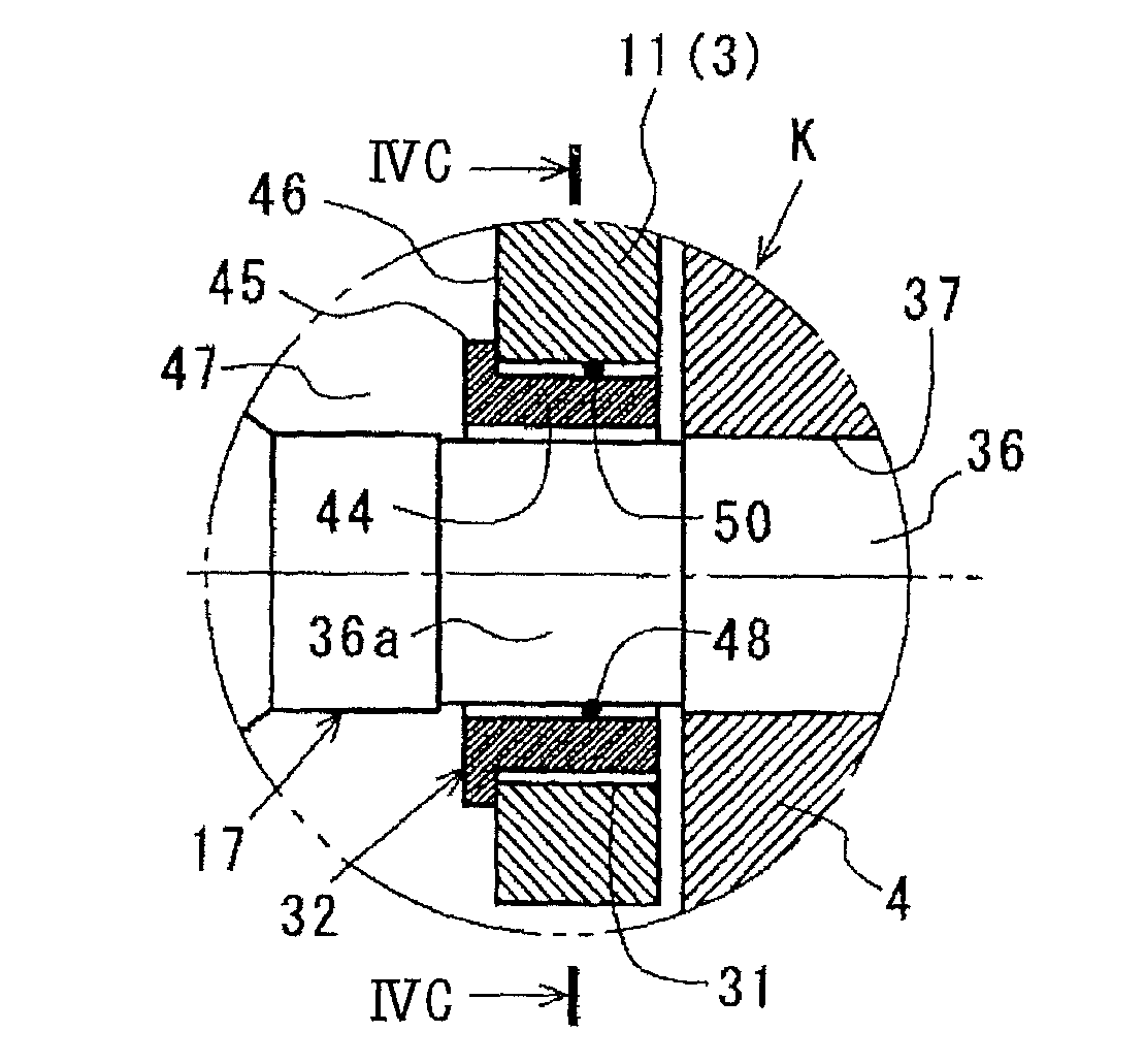
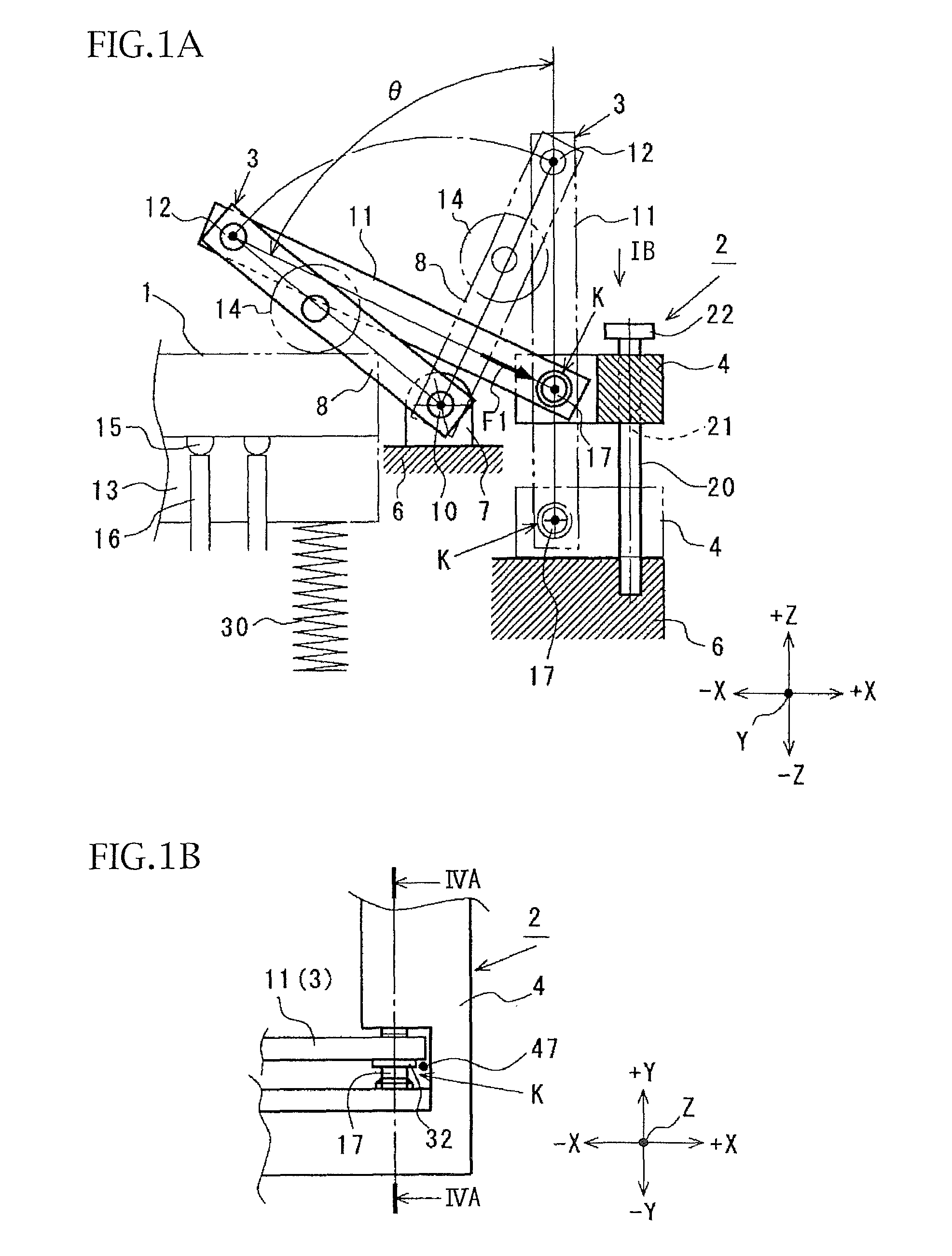
[0030]FIGS. 1 to 3 represent an electrical testing device for an IC package (i.e. IC socket) 2 to which an unlubricated bearing structure K according to an embodiment of the present invention is applied.

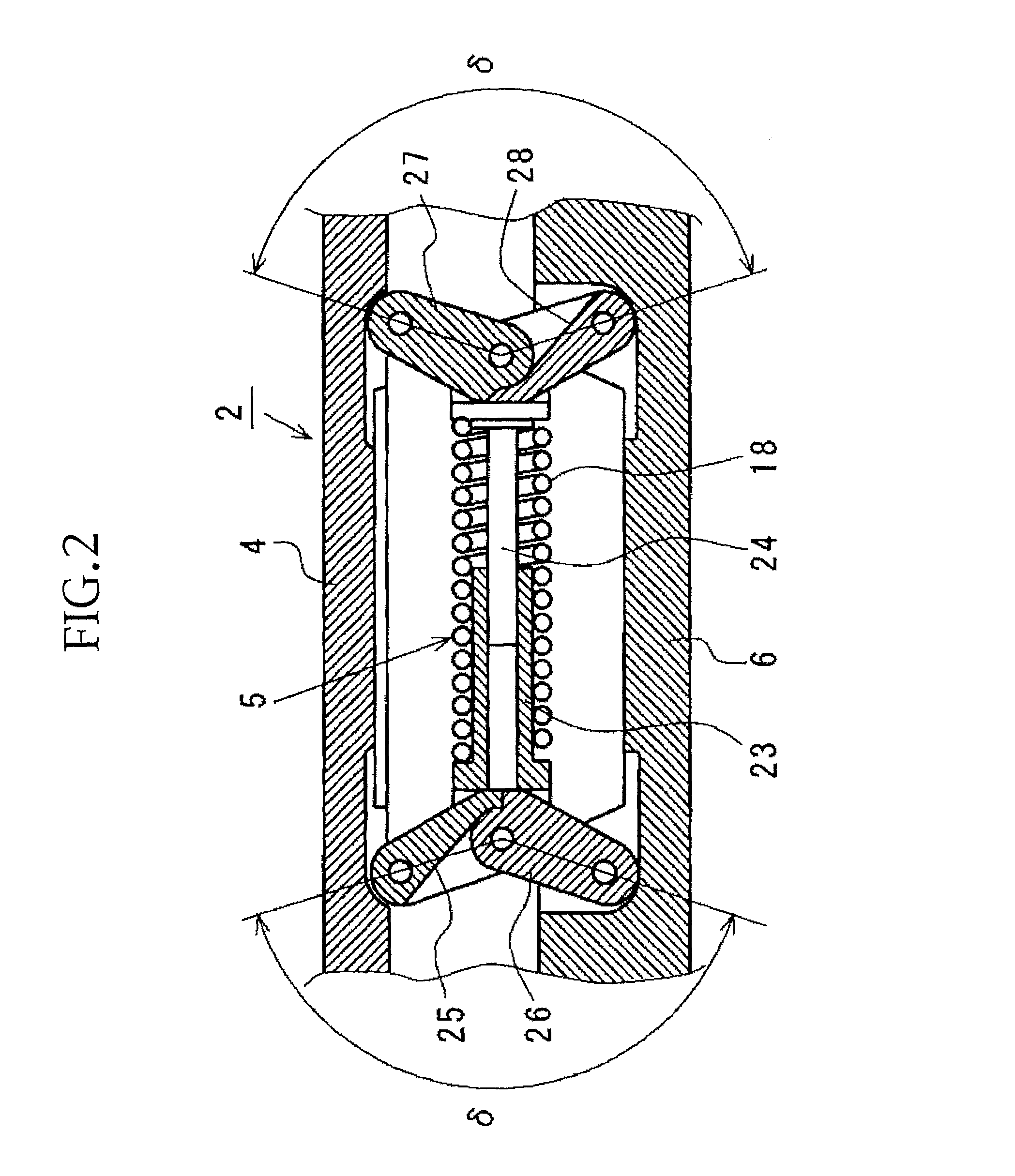
[0031]In the drawings, FIG. 1 is a view as a pattern diagram showing a portion (pressing mechanism 3 of the IC package) of the electrical testing device 2 for the IC package. FIG. 1B is a plan view showing an operating member 4 side of the IC package pressing mechanism 3 as viewed from an arrowed direction IB in FIG. 1A. FIG. 2 is a longitudinal cross-sectional view as a right side view in FIG. 1 and shows a first operating condition of an open / close support mechanism 5 of the electrical testing device 2 for the IC package 1. FIG. 3 shows a second operating condition of an open...


PUM


Abstract

An unlubricated bearing structure for supporting a rocking arm of an IC socket includes an arm support as an operating member that supports the rocking arm, a support shaft, made of metal, fitted and fixed to the arm support, and a cylindrical bush, made of metal, mounted to the support shaft so that the cylindrical bush is fitted into a bearing hole formed to the rocking arm. The support shaft, the cylindrical bush and the rocking arm are arranged such that a first clearance is formed between an outer peripheral surface of the support shaft and an inner peripheral surface of the cylindrical bush, and a second clearance is formed between an outer peripheral surface of the cylindrical bush and an inner peripheral surface of the bearing hole.

Description

BACKGROUND OF THE INVENTION[0001]1. Field of the Invention[0002]The present invention relates to an unlubricated bearing structure supporting a rocking arm to be swingable and to an IC socket using the same.[0003]2. Related Art[0004]FIG. 9 shows a conventional unlubricated bearing structure 100 of the type mentioned above. The unlubricated bearing structure 100 shown in FIG. 9 includes a bearing mount member 102 having an axial bearing hole 103, a cylindrical bush 101 which has an outer peripheral portion and which is pushed into the bearing hole 103, and a support shaft 104 which is fitted into the cylindrical bush 101 so that a clearance 105 exists between an inner peripheral portion of the cylindrical bush 101 and an outer peripheral portion of the support shaft 104 to thereby support the support shaft 104 to be rotatable by the bush 101 fixed to the bearing mount member 102 (refer to, for example, Japanese Patent Laid-open Publication No. SHO 62-242129, and JIS Machine Engineeri...

Claims


Application Information

Patent Timeline
Patent Type & Authority Patents(United States)
IPC IPC(8): H01R13/62
CPCF16C17/02G01R1/0466
Inventor HACHUDA, OSAMU
Owner ENPLAS CORP
Why Eureka
Try Eureka