Permanent magnet synchronous direct-driven motor bearing structure of the stirring industry

A permanent magnet synchronous and motor shaft technology, which is applied in the direction of electric components, casings/covers/supports, electrical components, etc., can solve the problems of accelerated gear wear, shortened life of the reducer, and low overall efficiency, and optimize the bearing structure , optimize the force condition, optimize the effect of the bearing span

Pending Publication Date: 2018-05-08
南京迪瓦机械制造有限公司
View PDF0 Cites 0 Cited by
  • Summary
  • Abstract
  • Description
  • Claims
  • Application Information

AI Technical Summary

Problems solved by technology

It has a series of problems such as low overall efficiency, high energy consumption, and high maintenance cost. Especially during the stirring process, the stirring impeller is subjected to a large bending moment and combined torque, which makes the bearing of the reducer quickly lose its rotation accuracy, which in turn causes bearing wear. , the gear wears faster, and the life of the reducer is shortened; therefore, the user's use and maintenance costs are increased, and the production efficiency is reduced.
[0003] In recent years, in the chemical mixing industry, the drive structure using permanent magnet synchronous direct drive motor + frequency converter has become more and more widespread. It has the advantages of high overall efficiency, low maintenance, and large overload start-up capability. , the bearing stress condition is bad. If no special design is made, the motor bearing will be damaged soon, which will cause damage to the motor and cause property loss of the user.

Method used


Image

  • Permanent magnet synchronous direct-driven motor bearing structure of the stirring industry
  • Permanent magnet synchronous direct-driven motor bearing structure of the stirring industry
  • Permanent magnet synchronous direct-driven motor bearing structure of the stirring industry

Examples


Embodiment 1

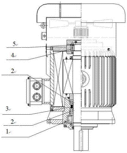
[0026] Such as figure 1 , figure 2 with image 3 As shown, the present invention provides a bearing structure for permanent magnet synchronous direct drive motors in the stirring industry. The bearing structure includes a shaft end bearing and a tail bearing. The shaft end bearing is arranged at one end of the motor shaft extension, and the tail The bearing is located at the tail of the motor.

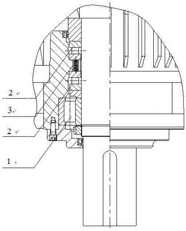
[0027] The shaft extension end bearing includes a set of cylindrical roller bearing 1 and two sets of cylindrical roller thrust bearings 2. The cylindrical roller bearing 1 and cylindrical roller thrust bearing 2 are arranged in sequence along the motor shaft extension end to the motor tail. An adjustment spring 3 is provided between the two sets of cylindrical roller thrust bearings 2, and the two sets of cylindrical roller thrust bearings 2 are arranged symmetrically relative to the adjustment spring 3; the adjustment springs.

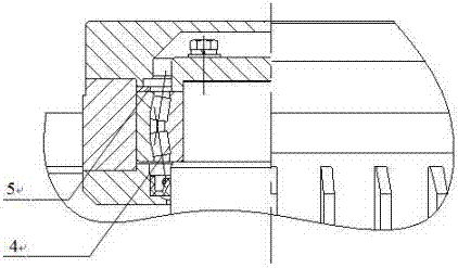
[0028] The tail bearing includes a set of self-alig...

Embodiment 2

[0032] Such as figure 1 , figure 2 with Figure 4 As shown, the present invention provides a bearing structure for permanent magnet synchronous direct drive motors in the stirring industry. The bearing structure includes a shaft end bearing and a tail bearing. The shaft end bearing is arranged at one end of the motor shaft extension, and the tail The bearing is located at the tail of the motor.

[0033] The shaft extension end bearing includes a set of cylindrical roller bearing 1 and two sets of cylindrical roller thrust bearings 2. The cylindrical roller bearing 1 and cylindrical roller thrust bearing 2 are arranged in sequence along the motor shaft extension end to the motor tail. An adjustment spring 3 is provided between the two sets of cylindrical roller thrust bearings 2, and the two sets of cylindrical roller thrust bearings 2 are arranged symmetrically relative to the adjustment spring 3; the adjustment springs.

[0034] The tail bearing includes a set of self-ali...

Embodiment 3

[0038] Such as figure 1 , figure 2 with Figure 5 As shown, the present invention provides a bearing structure for permanent magnet synchronous direct drive motors in the stirring industry. The bearing structure includes a shaft end bearing and a tail bearing. The shaft end bearing is arranged at one end of the motor shaft extension, and the tail The bearing is located at the tail of the motor.

[0039] The shaft extension end bearing includes a set of cylindrical roller bearing 1 and two sets of cylindrical roller thrust bearings 2. The cylindrical roller bearing 1 and cylindrical roller thrust bearing 2 are arranged in sequence along the motor shaft extension end to the motor tail. An adjustment spring 3 is provided between the two sets of cylindrical roller thrust bearings 2, and the two sets of cylindrical roller thrust bearings 2 are arranged symmetrically relative to the adjustment spring 3; the adjustment springs.

[0040] The tail bearing includes a set of self-ali...


PUM


Abstract

The invention discloses a special permanent magnet synchronous direct-driven motor bearing structure of the stirring industry. The permanent magnet synchronous direct-driven motor bearing structure ofthe stirring industry includes a shaft extension terminal bearing and a tail bearing, wherein the shaft extension terminal bearing includes a set of cylindrical roller bearings and two sets of cylindrical roller thrust bearings; an adjusting spring is arranged between the two sets of cylindrical roller thrust bearings; the tail bearing includes a set of self aligning bearings and an outer ring anti-rotation part; and the shaft extension terminal bearing and the tail bearing take actions together so as to bear the weight of a motor rotor, the weight of a stirring paddle, the unilateral magnetic pull, the axial imbalance magnetic pull, the reaction axial force of stirring liquid to the stirring paddle, and the radial force of stirring liquid to the stirring paddle, so as to guarantee that the motor can operate stably and reliably.

Description

technical field [0001] The invention relates to a permanent magnet synchronous direct drive motor bearing, in particular to a permanent magnet synchronous direct drive motor bearing structure used in the stirring industry. Background technique [0002] At present, domestic chemical mixing enterprises mainly use the structure of ordinary motor + reducer, and the bearing of the reducer adopts a pair of tapered roller bearings. It has a series of problems such as low overall efficiency, high energy consumption, and high maintenance cost. Especially during the stirring process, the stirring impeller is subjected to a large bending moment and combined torque, which makes the bearing of the reducer quickly lose its rotation accuracy, which in turn causes bearing wear. , gear wear is accelerated, and the life of the reducer is shortened; therefore, the user's use and maintenance costs are increased, and production efficiency is reduced. [0003] In recent years, in the chemical mi...

Claims


Application Information

Patent Timeline
IPC IPC(8): H02K5/173H02K7/08
CPCH02K5/1732H02K7/083
Inventor 朱见昌
Owner 南京迪瓦机械制造有限公司
Why Eureka
Try Eureka