Dual-mass flywheel

a flywheel and double-mass technology, applied in the direction of couplings, bearing unit rigid supports, slip couplings, etc., can solve the problems of low rigidity in the bending direction of the axle, large radial dimension, and low cost, and achieve the effect of improving the bearing structur

Inactive Publication Date: 2008-11-04
EXEDY CORP
View PDF9 Cites 1 Cited by
  • Summary
  • Abstract
  • Description
  • Claims
  • Application Information

AI Technical Summary

Benefits of technology

[0011]An object of the present invention is to improve a bearing structure for a dual-mass flywheel.
[0013]A needle bearing is used as a bearing to support the second flywheel to be able to rotate on a member on the crankshaft side in this dual-mass flywheel, and durability is therefore enhanced and clearance management facilitated.
[0014]A dual-mass flywheel according to a second aspect of the present invention is the dual-mass flywheel of the first aspect, wherein the plurality of needles is in direct contact with at least one of the peripheral surfaces of either the second flywheel or the member on the crankshaft side. In this dual-mass flywheel, the plurality of needles is in direct contact with the peripheral surface, so there is no need for an inside and outside wheel in that portion. The number of parts is therefore reduced, and the structure is simplified.
[0015]A dual-mass flywheel according to a third aspect of the present invention is the dual-mass flywheel of the first or second aspects, wherein the needle bearing also has a retainer to hold the plurality of needles. In this dual-mass flywheel, the plurality of needles is held by the retainer, so the positioning in the circumferential direction of the plurality of needles is stabilized.
[0016]A dual-mass flywheel according to a fourth aspect of the present invention is the dual-mass flywheel of any of the first to third aspects, wherein the needle bearing further has a lubricant filled into the space between the peripheral surfaces that contain the bearing, and also has a seal member to seal the lubricant in the space. In this dual-mass flywheel, a lubricant is filled into the space in which the needle bearing is contained, so friction in the bearing portion is reduced.
[0019]A dual-mass flywheel according to a seventh aspect of the present invention is the dual-mass flywheel of any of the first to sixth aspects that is further provided with a retaining member to prevent the plurality of needles from escaping or moving from the space. In this dual-mass flywheel, the plurality of needles is prevented from escaping by the retaining member.

Problems solved by technology

A ball bearing, as such, has drawbacks in that it has a relatively high cost and that its large radial dimension occupies a relatively large amount of space.
A ball bearing also inherently has low rigidity in the bending direction of the axle, and is therefore unable to create adequate resistance to bending vibrations when a dual-mass flywheel is used.
A bushing has low wear resistance and the clearance thereof is difficult to manage, so the gap between the bushing and the peripheral surfaces of the first and second flywheels can easily become unnecessarily large.

Method used


Image

  • Dual-mass flywheel
  • Dual-mass flywheel
  • Dual-mass flywheel

Examples


first embodiment

Overall Structure

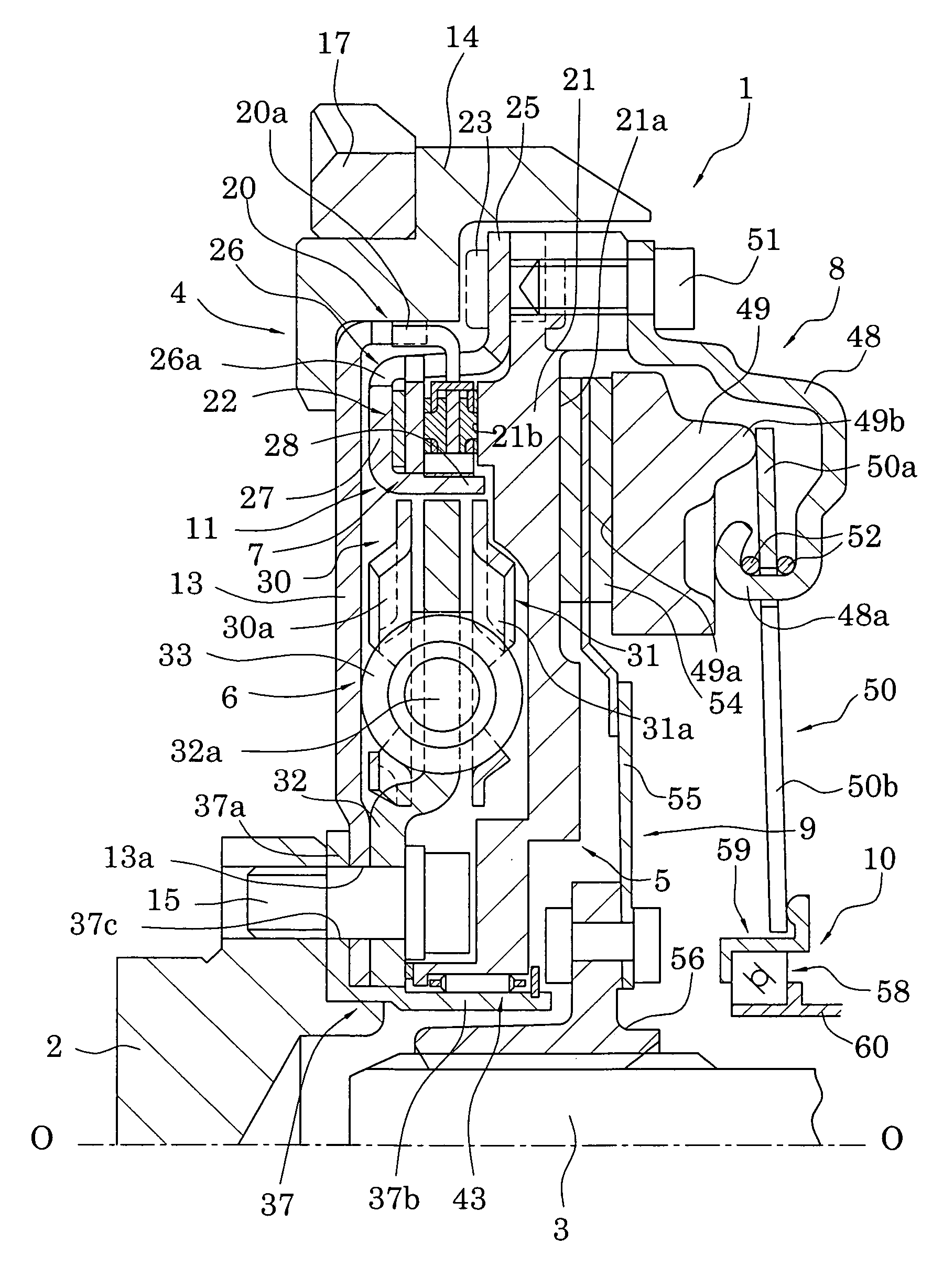
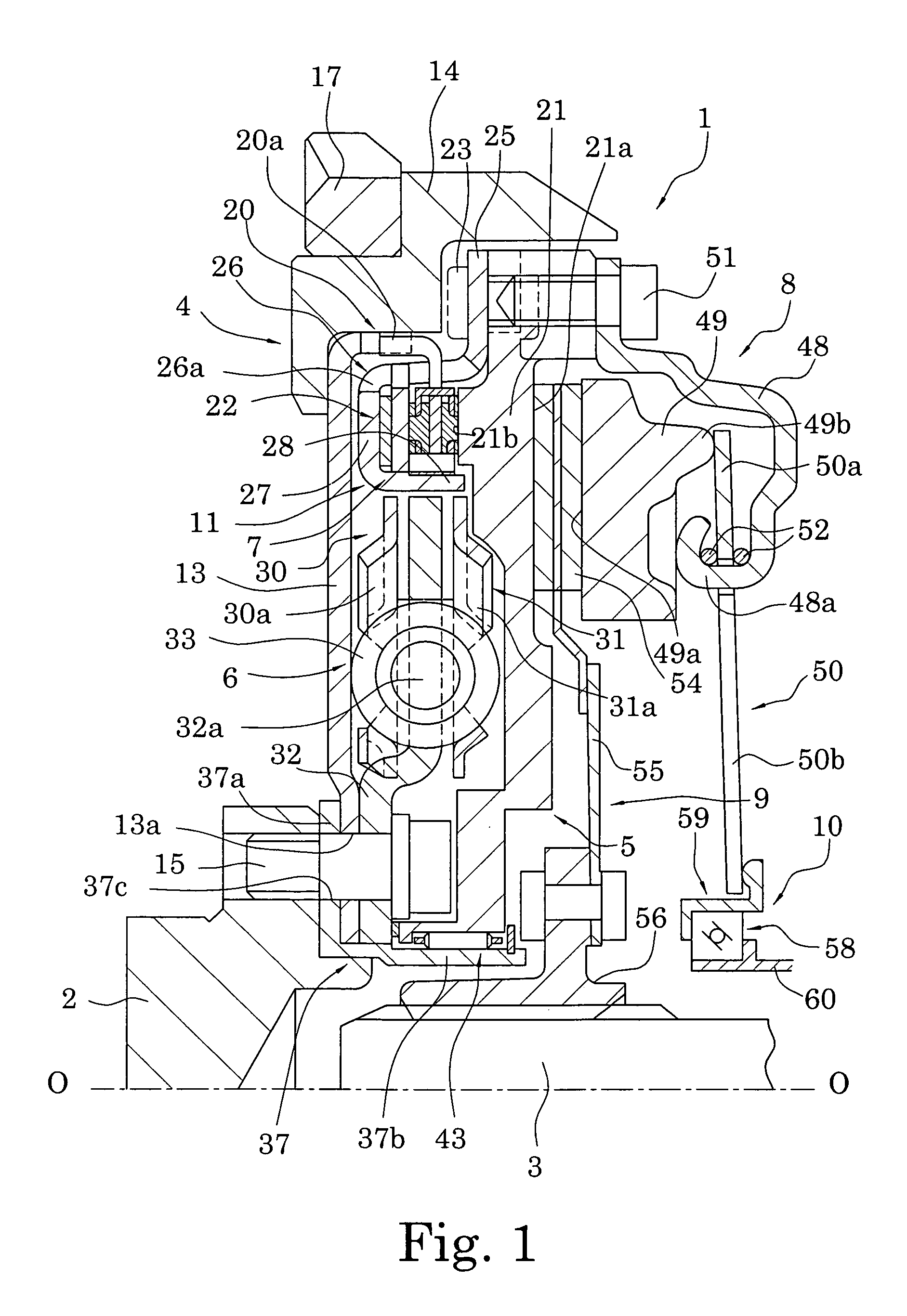
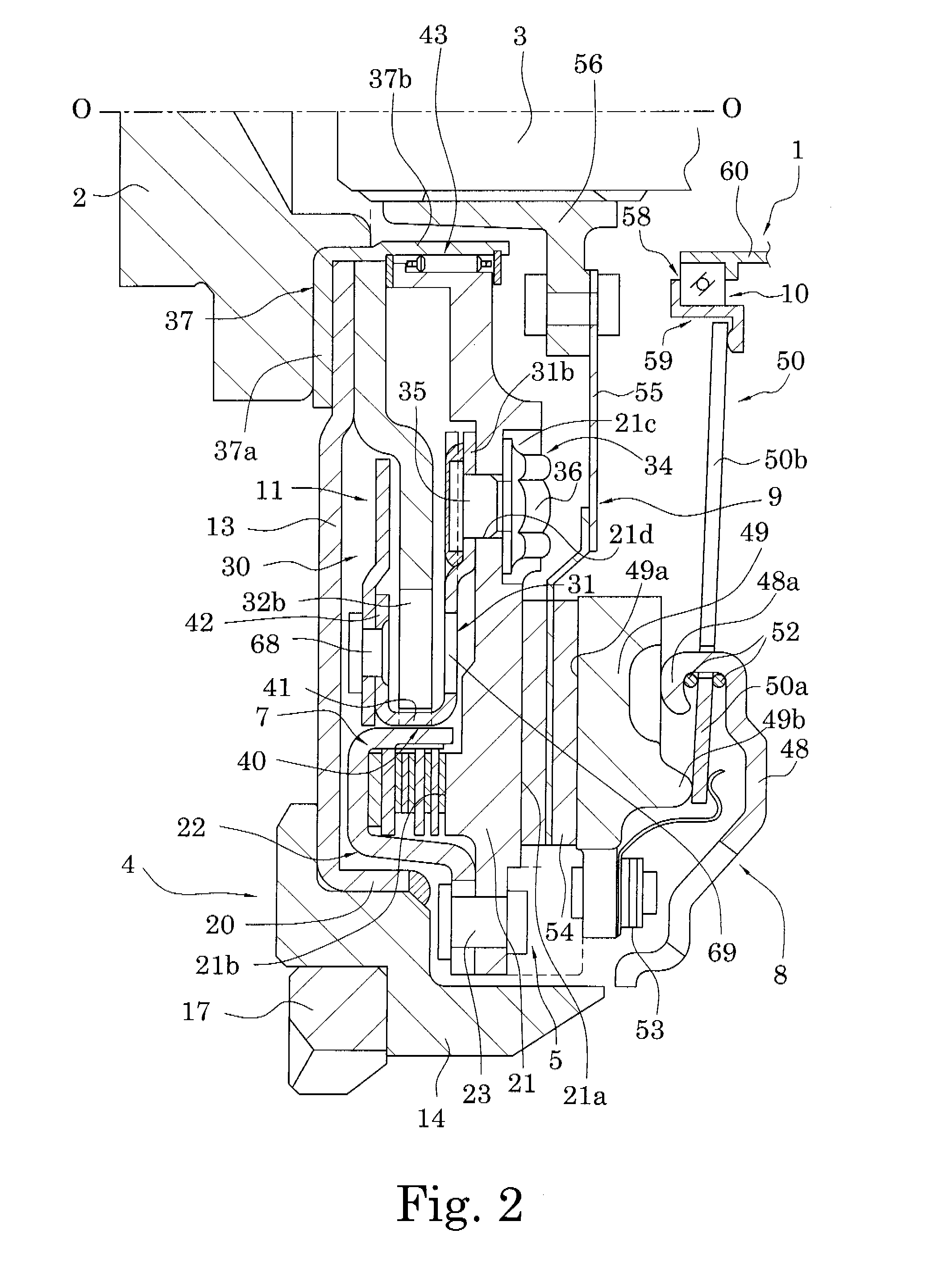
[0030]As shown in FIGS. 1 through 3, a clutch device 1 in accordance with a preferred embodiment of the present invention is configured to transmit and to interrupt torque between a crankshaft 2 on an engine side and an input shaft 3 on a transmission side. The clutch device 1 is primarily formed of a first flywheel assembly 4, a second flywheel assembly 5, a clutch cover assembly 8, a clutch disk assembly 9, and a release device 10. The first and second flywheel assemblies 4 and 5 are combined to form a flywheel damper 11, which includes a damper mechanism 6 and is described later.

[0031]In FIGS. 1 and 2, O-O indicates a rotation axis of the clutch device 1. An engine (not shown) is disposed on the left side in FIGS. 1 and 2, and a transmission (not shown) is disposed on the right side. In following description, the left side in FIGS. 1 and 2 will be referred to as the engine side, which is based on the axial direction, and the right side will be referred to the tra...


PUM


Abstract

A flywheel assembly with an improved bearing structure is provided. The flywheel damper (11) is a flywheel assembly for transmitting torque from the crankshaft of an engine, and has a first flywheel assembly (4), a second flywheel assembly (5), a damper mechanism (6), and a needle bearing (43). The first flywheel assembly (4) is fixed to the crankshaft (2). The second flywheel assembly (5) is disposed so as to be able to rotate relative to the first flywheel assembly (4). The damper mechanism (6) elastically connects the second flywheel assembly (5) to the crankshaft (2) in the rotation direction. The needle bearing (43) is a bearing to support rotatably the second flywheel assembly (5) on the crankshaft (2), and has a plurality of needles (44) disposed between the peripheral surfaces (21d) and (37b) of both members.

Description

BACKGROUND OF THE INVENTION[0001]1. Field of the Invention[0002]The present invention relates to a dual-mass flywheel. More specifically, the present invention relates to a dual-mass flywheel whereby a second flywheel is elastically connected in the rotation direction with a member on the crankshaft side.[0003]2. Background Information[0004]Conventionally, a flywheel is attached to a crankshaft of an engine to absorb vibrations caused by variations in engine combustion. Further, a clutch device is arranged on a transmission side (i.e., in a position axially shifted toward the transmission) with respect to the flywheel. The clutch device usually includes a clutch disk assembly coupled to an input shaft of the transmission, and a clutch cover assembly to bias the frictional coupling portion of the clutch disk assembly toward the flywheel. The clutch disk assembly typically has a damper mechanism for absorbing and damping torsional vibrations. The damper mechanism has elastic members s...

Claims


Application Information

Patent Timeline
Patent Type & Authority Patents(United States)
IPC IPC(8): F16F15/121F16D13/68F16C19/46F16C33/78F16C33/60F16C33/66F16C33/76F16C35/07F16D7/00F16F15/131F16F15/30
CPCF16C19/46F16C33/605F16C33/76F16C33/7809F16F15/13171F16C2361/55F16F15/30
Inventor YAMAMOTO, KOZOTSURUTA, HIROYOSHI
Owner EXEDY CORP
Why Eureka
Try Eureka