
Pivoting support arrangement for maintaining a bicycle wheel in an upright position

a technology of supporting arrangement and bicycle wheel, which is applied in the field of vehicle-mounted bicycle carriers, can solve the problems of time and effort consuming for bicycle users, not well suited for use with this type of carrier, and not well suited for use with suspension-type carriers

Inactive Publication Date: 2007-05-29
PEDRINI FABIO
View PDF63 Cites 27 Cited by
  • Summary
  • Abstract
  • Description
  • Claims
  • Application Information

AI Technical Summary

Benefits of technology

[0005]It is an object of the present invention to provide a ride-ready bicycle carrier capable of quickly and easily mounting various types and sizes of bicycles. It is a further object of the invention to provide such a bicycle carrier which is capable of supporting the bicycle in a hands-free manner when the bicycle is initially engaged with the carrier. A still further object of the invention is to provide such a bicycle carrier which incorporates a stabilizing member configured and arranged to provide positive engagement of the bicycle wheel with the carrier. Yet another object of the invention is to provide such a bicycle carrier which engages one of the bicycle wheels in a similar engagement configuration for all sizes of bicycle wheels. A still further object of the invention is to provide such a bicycle carrier which obstructs access to a quick release mechanism associated with the bicycle wheel, to prevent theft of the bicycle when engaged with the carrier. A still further object of the invention is to provide such a bicycle carrier which is relatively simple in its components and construction, and which provides quick and easy mounting of the bicycle to the carrier while providing positive engagement of the bicycle with the carrier so as to prevent movement of the bicycle during transport.
[0007]Each wheel engagement member preferably has an arcuate wheel engagement surface engageable with the wheel. The stabilizing member is preferably located between the wheel engagement members, and is oriented so as to apply a downward force on the wheel at a location between the wheel engagement members. With this construction, the stabilizing member and the wheel engagement members provide three-point securement of the wheel to the carrier, to stabilize the bicycle when mounted to the carrier. The wheel engagement areas are preferably configured so as to grip the side areas of the wheel when the wheel is initially placed into engagement with the wheel engagement members, to provide a self-supporting feature for allowing the user to operate the stabilizing member without having to stabilize the bicycle with one hand.
[0009]The base portion may be mounted to the structural member of the carrier for pivoting movement between a raised position and a lowered position. When in the raised position, the base portion extends vertically upwardly from the structural member between the wheel engagement members, and the arm is extendible and retractable in a vertical direction relative to the base portion. A blocking mechanism is interposed between the arm and the base portion for preventing the arm from being moved downwardly into engagement with the wheel unless the arm is in its upright position. In this manner, it is ensured that the arm is in a vertical orientation between the wheel engagement members, so as to apply a vertical downward force on the wheel between the engagement members when the arm is retracted to move the wheel engaging area of the arm into engagement with the wheel. When the base portion is in its upright position, an upper end of the base portion is in alignment with and located adjacent the hub of the wheel, due to the centering of the wheel between the pivoting wheel engagement members. The presence of the base portion prevents movement of the quick release lever of the wheel to a release position, so as to ensure that the bicycle cannot be disengaged from the wheel when the bicycle is mounted to the carrier.

Problems solved by technology

While these types of bicycle carriers provide secure and stable engagement of the bicycle with the carrier, the requirement to remove the front wheel of the bicycle entails time and effort which is inconvenient to the bicycle user.
While these types of bicycle carriers function satisfactorily for many types of bicycles, many bicycle frames do not have a conventionally configured top tube, and are thus not well suited for use with this type of carrier.
While this type of support arrangement provides stability against swinging movement and also provides a flexible mounting arrangement for various types of bicycle frames, there nonetheless are certain frame designs which simply are not well suited for use with suspension-type carriers.
Further, while this system provides a certain amount of stability against swinging movement of the bicycles during transport, it remains possible for certain components of the bicycle, e.g. the front wheels, to come into contact during transport since such components are not stabilized against movement when the bicycle is engaged with the carrier.
While the design illustrated in the '893 patent is capable of mounting a bicycle in a ride-ready fashion to a vehicle, it is disadvantageous in that the bicycle is not supported when the bicycle is initially engaged with the carrier.
While the design in the '659 patent is operable to engage the bicycle with the carrier in a ride-ready fashion, it is also somewhat disadvantageous in that the frame structure, which provides initial support for the bicycle when engaged with the carrier, involves heavy tubular members which are specially formed to define the wheel well and the remaining portions of the frame.
The rack thus has a significant amount of weight, and has associated costs of manufacture which are significant in view of the amount of material required and the number of forming steps involved in manufacturing the frame.
Further, the designs in both the '659 and '893 patents leave the wheel hub exposed, which makes it possible to access the wheel hub and to utilize the quick-release mechanism of the wheel hub to disengage the bicycle frame from the wheel, which can lead to theft of the bicycle when mounted to the carrier.

Method used


Image

  • Pivoting support arrangement for maintaining a bicycle wheel in an upright position
  • Pivoting support arrangement for maintaining a bicycle wheel in an upright position
  • Pivoting support arrangement for maintaining a bicycle wheel in an upright position

Examples


Embodiment Construction

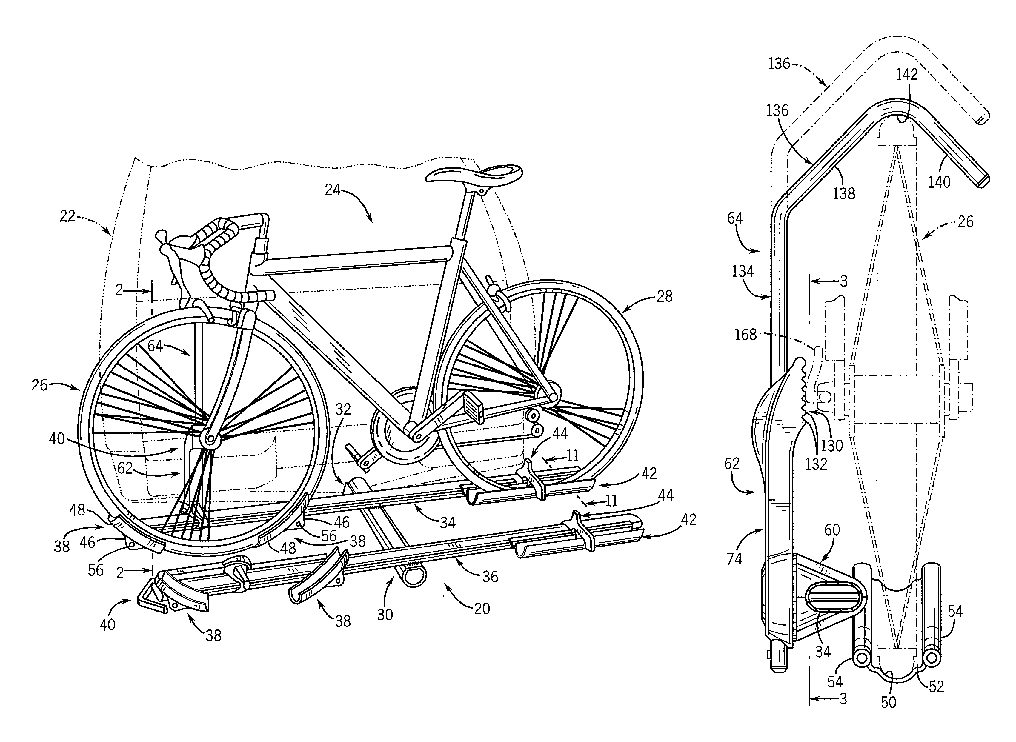
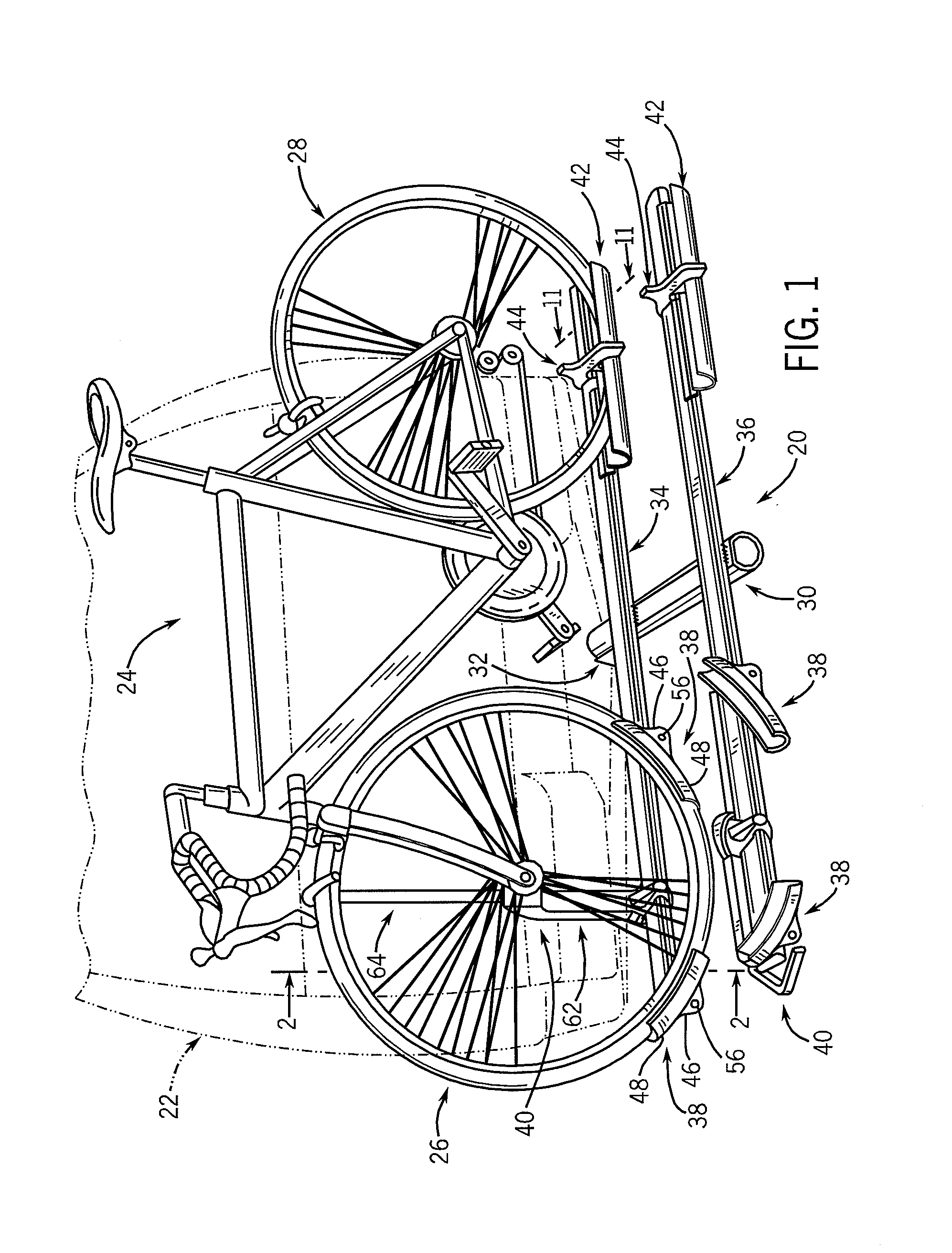
[0030]FIG. 1 illustrates a bicycle rack or carrier 20 adapted for mounting to the hitch of a vehicle, shown at 22, for transporting a bicycle 24. Bicycle carrier 20 is adapted to carry bicycle 24 in a ride-ready fashion, and provides quick and easy mounting of bicycle 24 to carrier 20 and removal of bicycle 24 from carrier 20. In a manner to be explained, carrier 20 engages the front and rear wheels, shown at 26, 28, respectively, of bicycle 24 for retaining bicycle 24 in position on carrier 20.

[0031]Carrier 20 includes an axial central support member 30, in the form of a tubular member, which extends rearwardly from a hitch attachment mechanism 32 adapted for engagement with the trailer hitch of vehicle 22. Hitch attachment mechanism 32 may be in the form of a mounting bracket to which central support member 30 is connected for movement between and operative extended position as shown, and an inoperative stowed position in which central support member 30 is positioned in an upright...


PUM


Abstract

A ride ready vehicle-mounted bicycle carrier includes a pair of spaced apart wheel supports and a stabilizing member which is engageable with the bicycle, preferably with one of the bicycle wheels, at a location above the wheel supports. One of the wheel supports is in the form of a pair of spaced apart wheel engagement members which are pivotably mounted to a structural member associated with the carrier, and which are configured to grip the wheel so as to provide initial support for the bicycle on the carrier. The stabilizing member is in the form of a clamp arm mechanism having a base mounted to the structural member and an extendible and retractable arm having a wheel-engaging portion at its outer end, which can be moved into and out of engagement with the wheel. The clamp arm mechanism is located between the wheel support members, and is arranged to apply a vertical downward force on the wheel at a location between the wheel engagement members, to provide a secure three-point engagement of the wheel and thereby to provide stable mounting of the bicycle to the carrier.

Description

CROSS-REFERENCE TO RELATED APPLICATION[0001]This application is a continuation of application Ser. No. 10 / 156,378 filed May 28, 2002, now U.S. Pat. No. 6,761,297, which claims the benefit of U.S. Provisional Application Ser. No. 60 / 314,428 filed Aug. 23, 2001.BACKGROUND AND SUMMARY OF THE INVENTION[0002]This invention relates to vehicle-mounted bicycle carriers, and more particularly to a bicycle carrier which allows the bicycle to be mounted to the carrier in a ride-ready fashion, without the need to remove one of the bicycle wheels.[0003]Various types of vehicle-mounted bicycle carriers are known, which enable a bicycle to be transported on a vehicle. Fork mount bicycle carriers typically have a rear wheel support and require the user to disengage the front wheel of the bicycle using a conventional quick release mechanism associated with the hub of the bicycle wheel. While these types of bicycle carriers provide secure and stable engagement of the bicycle with the carrier, the req...

Claims


Application Information

Patent Timeline
IPC IPC(8): B60R9/00B60R9/10
CPCB60R9/10Y10S224/924
Inventor PEDRINI
Owner PEDRINI FABIO
Learn More