Structural members and joining arrangements therefor

a structural member and joining arrangement technology, applied in the direction of couplings, rod connections, manufacturing tools, etc., can solve the problems of weak structural structure of the stud frame, ineffective bracing, and inability to place reliance, so as to improve the structural strength, quick and efficient joining, and quick and efficient and infinite positioning of the stud

a structural member and joining arrangement technology, applied in the direction of couplings, rod connections, manufacturing tools, etc., can solve the problems of weak structural structure of the stud frame, ineffective bracing, and inability to place reliance, so as to improve the structural strength, quick and efficient joining, and quick and efficient and infinite positioning of the stud

US7223043B1Inactive Publication Date: 2007-05-29TSF SYST

Image

  • Structural members and joining arrangements therefor
  • Structural members and joining arrangements therefor
  • Structural members and joining arrangements therefor

Examples


Embodiment Construction

[0058]The present invention will not be described according to preferred but non limiting embodiments and with reference to the accompanying illustrations wherein;

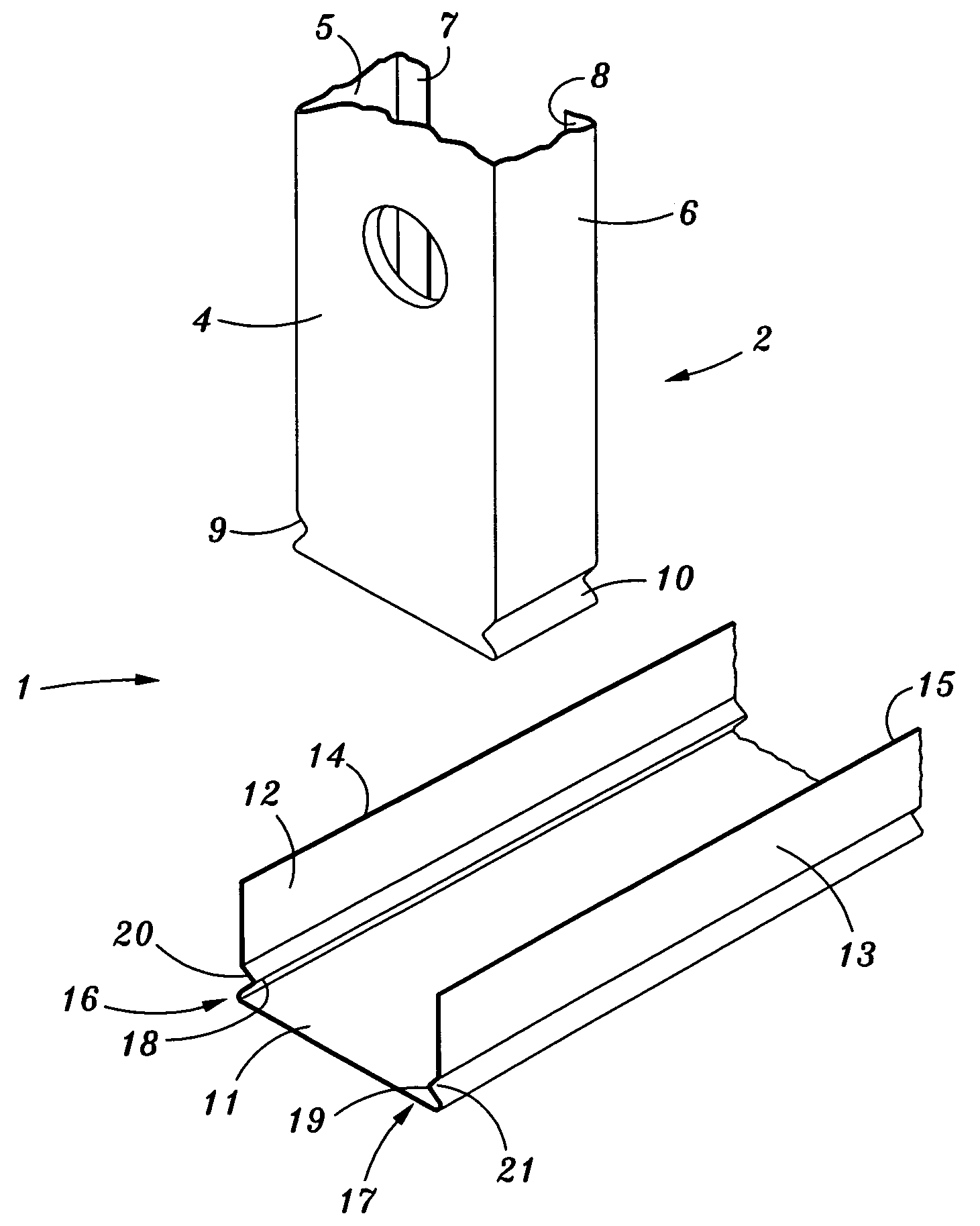
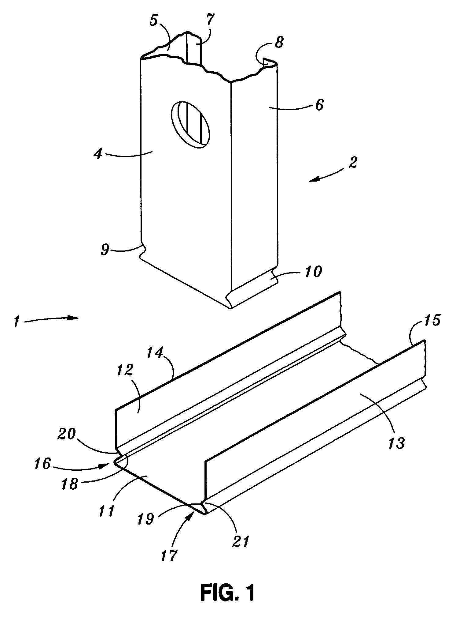
[0059]FIG. 1 shows an exploded view of a joining arrangement for two structural members including respective formations in the walls of the members according to a preferred embodiment of the invention;

[0060]FIG. 2 shows a perspective view of respective ends of a typical stud and plate according to one embodiment of the invention prior to engagement.

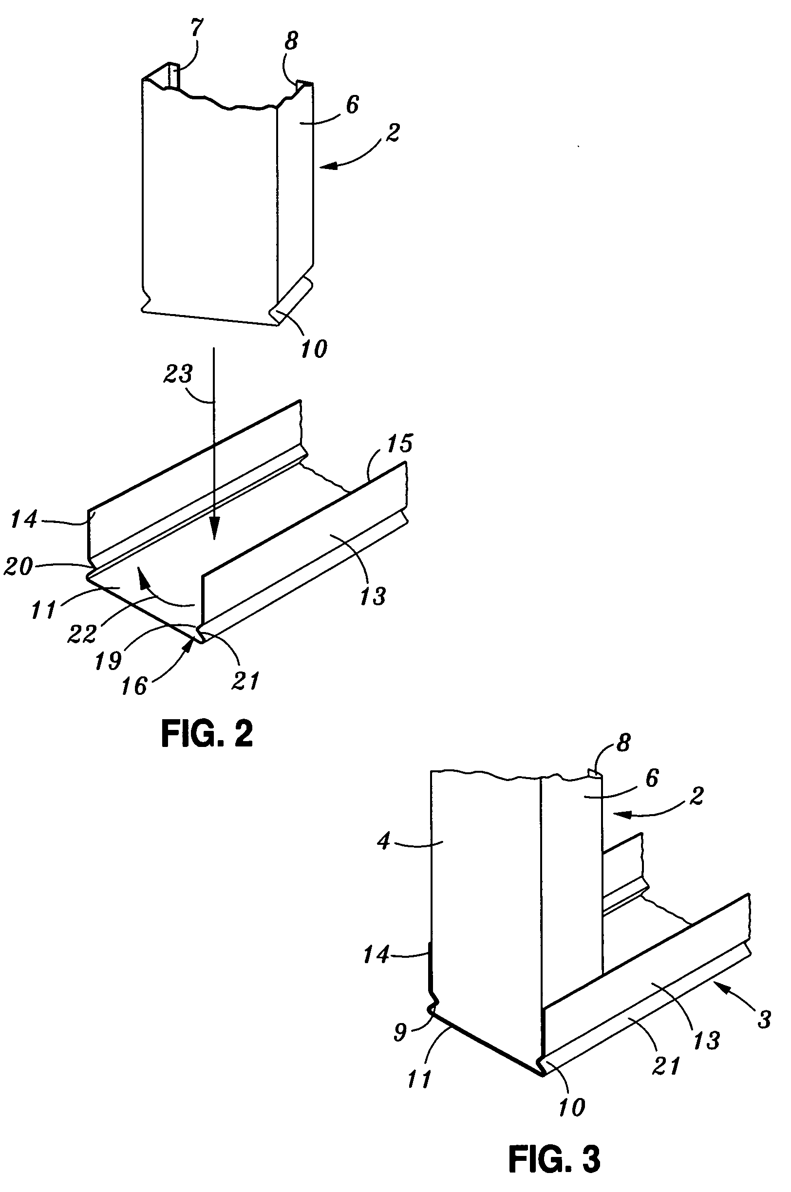
[0061]FIG. 3 shows an assembled view of the arrangement in FIGS. 1 and 2.

[0062]FIG. 4 shows an elevation view of a typical stud and plate frame according to a preferred embodiment of the invention.

[0063]FIG. 5 shows a perspective view of an engagement between an intermediate stud and bottom plate in the frame of FIG. 4.

[0064]FIG. 6 shows an end view of the arrangment of FIG. 5.

[0065]FIG. 7 shows an isometric view of a telescopic stud member according to a preferred embodiment of...


PUM


Abstract

A joining arrangement for use in the construction of stud frames and for releasable attachment of a first member to a second structural member forming part of the frame. The first member includes in at least one side wall a female recess which, when the members are joined, engages a corresponding male protrusion in at least one wall of the second member. The respective formations in the first and second members engage such that they are generally in alignment thereby securing the first member to the second member and wherein the first member is a stud and the second member is a plate.

Description

BACKGROUND[0001]The present invention relates to joining systems and to structural members for use in such joining systems. More particularly, the present invention relates to structural members for use in releasable joining arrangements formed by such structural members whereby an end of a first structural member includes a formation which may be joined by engagement with a corresponding formation on a second structural member such that the members may be joined at any location along the length of the second member and without the need for fasteners. Although the present invention in all its forms has multiple applications, the invention will be primarily described with reference to its application in joining structural members for use in particular thought not exclusively in stud frames.PRIOR ART[0002]Traditionally, light weight construction of metal stud frames employs steel or aluminium stud members which are generally channel shaped and wherein the ends of the stud members enga...

Claims


Application Information

Patent Timeline
29 May 2007
Publication
US7223043B1
IPC
E04B1/58; E04B1/24; E04B2/58; E04B2/76; E04B2/78
CPC
E04B2/766; E04B2/789; Y10T403/4605; Y10T403/46; Y10T403/7043; E04B2/7459; E04B2/767; F16B7/0486
Inventors
ANDREWS, WILLIAM