Door frame miter brace

a technology of miter braces and door frames, which is applied in the direction of curtain suspension devices, manufacturing tools, building scaffolds, etc., can solve the problems of increasing the number of fastening devices currently being used at the junction of the members, requiring extra time, care and skill, and many of them are generally inadequate to provide proper alignment or positive engagemen

Inactive Publication Date: 2007-05-29
ANCHOR TOOL & DIE
View PDF7 Cites 28 Cited by
  • Summary
  • Abstract
  • Description
  • Claims
  • Application Information

AI Technical Summary

Benefits of technology

[0004]The present invention overcomes these and other disadvantages of prior art frame assemblies by providing a frame miter brace which ensures proper alignment and registration of adjoining frame members for ease of installation and assembly. The frame miter brace of the invention also serves as an assembly jig by which intersecting frame members are accurately aligned and held prior to being welded together into a one piece assembly.

Problems solved by technology

Many of the fastening devices currently being used at the junction of the members are generally inadequate to provide proper alignment or positive engagement with one another.
This is particularly problematic in that it requires extra time, care and skill during installation by the workmen in achieving the common right angle joint for proper fit appearance when complete.

Method used


Image

  • Door frame miter brace
  • Door frame miter brace
  • Door frame miter brace

Examples


Embodiment Construction

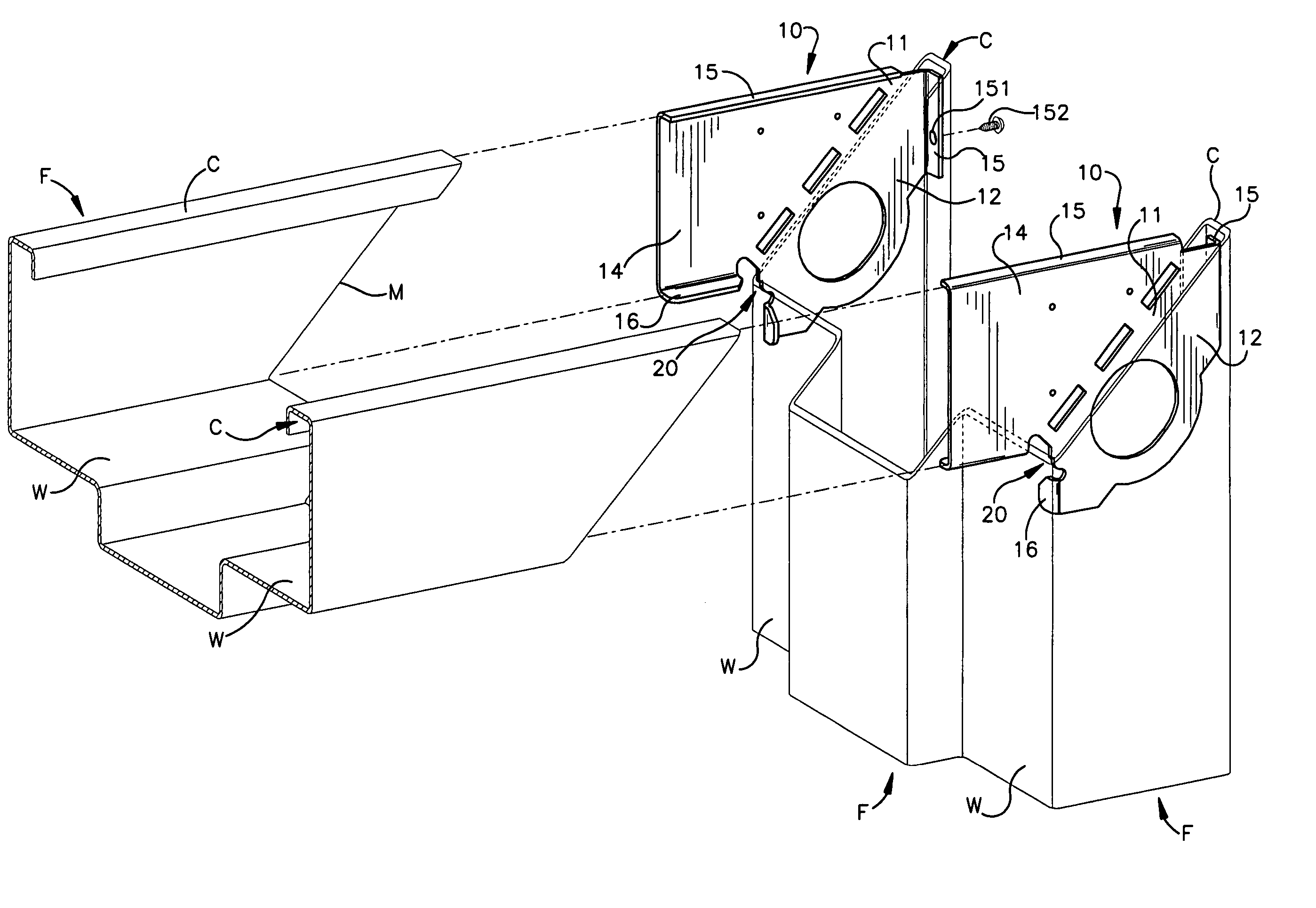
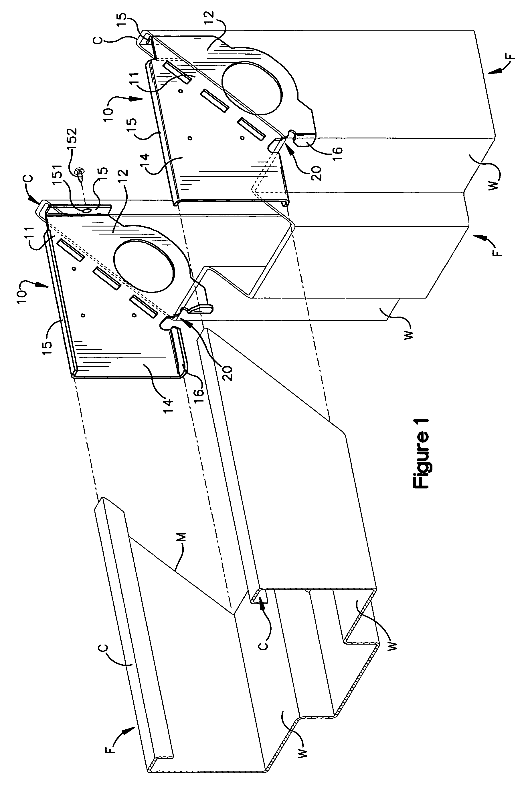
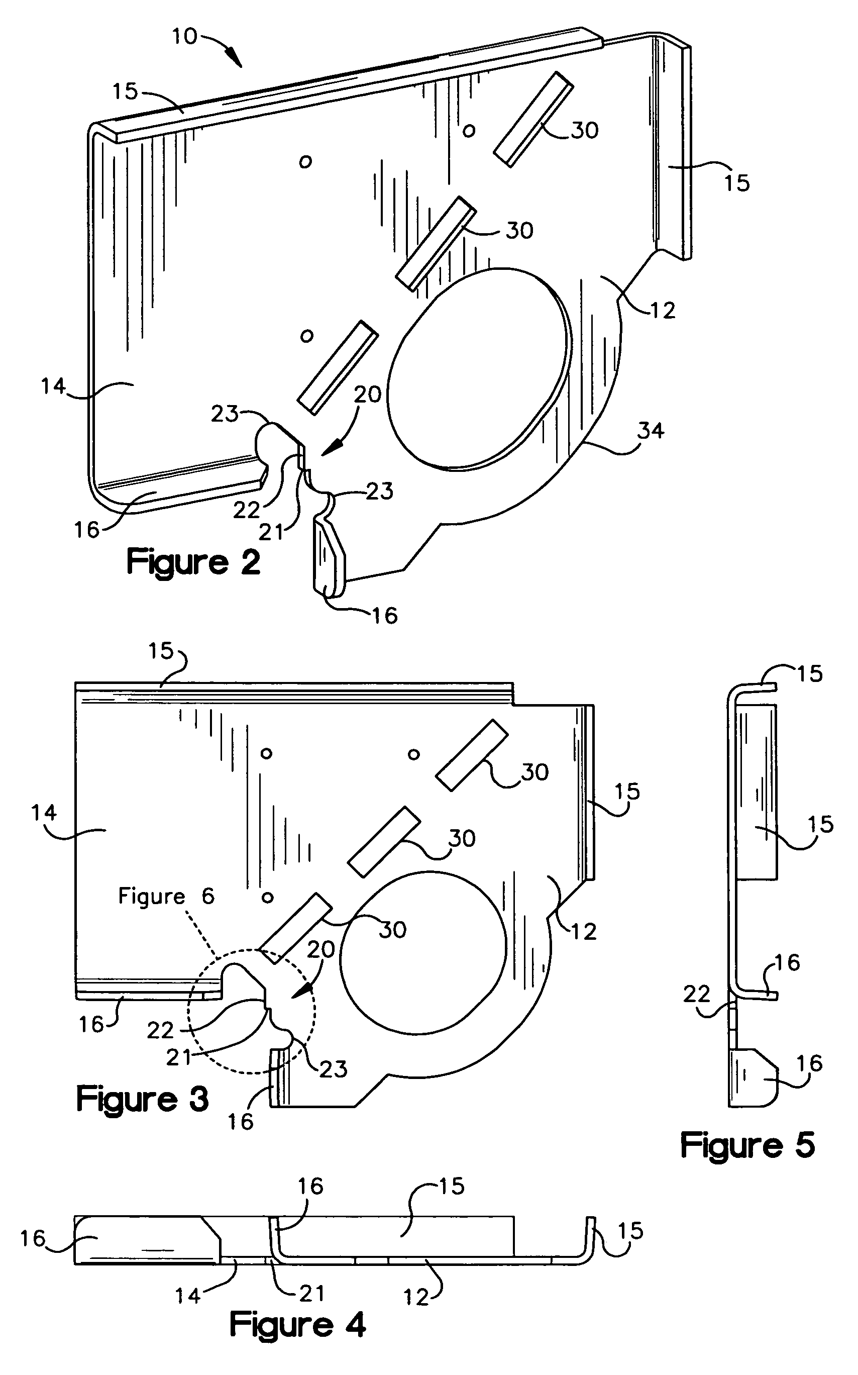
[0015]As shown in the Figures, a frame miter brace or guide, indicated generally at 10, for placement at a mitered joint or intersection of frame members, such as frame members used to define an opening such as a doorway, window or other type of opening, has a body 11 with a first leg 12 and a second leg 14, the first and second legs generally extending in orthogonal directions, though other angular orientations of the legs are contemplated by the invention. The body 11 is generally planar, as shown in FIGS. 4 and 5, but can be made in different cross-sectional thicknesses. As shown in FIG. 1, the legs 12 and 14 are configured to fit frame members F which intersect to from a door or window frame or other structure. More specifically, flanges 15 and 16 are formed at the edges of opposing sides of the legs 12, 14, with a major flange 15 configured to fit within channel C of the frame members, and a minor flange 16 configured to contact the jamb wall W of the frame member. In the embod...


PUM


Abstract

A frame member miter guide or brace has first and second legs configured for insertion and engagement with adjoining frame members at a mitered joint, the miter guide having a stop with stop edges which accurately position intersecting walls of the frame members for precise alignment of the mitered joint. Stop edges of the stop correspond with the correct positions of the frame members, so that the members are held in place for final attachment and installation. Positive engagement of edges of the frame member walls with the stop edges insures highly accurate orientation of the mitered joint. A fracture line for welded installation of the frame members, and a leg profile which minimizes damage in handling and installation is also described.

Description

FIELD OF THE INVENTION[0001]The present invention pertains generally to hardware and fastener components, and more particularly to hardware and fastener components which are used in building construction applications.BACKGROUND OF THE INVENTION[0002]In architectural applications and building construction there are frame structures for doorways, windows or other openings formed by frame members which must be assembled at right angles. Precise angles are required whereby the mating edges provide a hairline joint having a permanent neat and trim appearance. Many of the fastening devices currently being used at the junction of the members are generally inadequate to provide proper alignment or positive engagement with one another.[0003]One example of such a fastening device is described in U.S. Pat. No. 3,552,085, which includes a corner clip which works in cooperation with jamb anchors to establish a frame miter. For example the use of a triangular piece at the intersection of right an...

Claims


Application Information

Patent Timeline
Patent Type & Authority Patents(United States)
IPC IPC(8): E04G7/00E06B3/988
CPCE06B3/9885Y10T403/725Y10T403/72Y10T403/42Y10T403/73F16B2200/67F16B2200/65
Inventor QUINTILE, MARK J.
Owner ANCHOR TOOL & DIE
Why Eureka
Try Eureka