Collecting bag having an improved closure

a technology of closure device and bag, which is applied in the field of collecting bags, can solve the problems of limited design of locking device, reduced dexterity of users, and inconvenient folding operation, and achieves the effects of convenient folding operation, sufficient tightness, and increased heigh

Active Publication Date: 2007-05-29
COLOPLAST AS
View PDF17 Cites 40 Cited by
  • Summary
  • Abstract
  • Description
  • Claims
  • Application Information

AI Technical Summary

Benefits of technology

[0014]By the combination of forming the plate members from a relatively stiff material and the positions of the plate members with respect to each other, i.e. with a small distance between the plate members in the longitudinal direction of the discharge portion, the folding operation is facilitated even in case of wide discharge portions. Surprisingly, it turns out that sufficient tightness is achieved, even though virtually no deformation of the plate members in the thickness direction takes place. During the folding of the discharge portion the distal edge of the first plate member provides a pivot which, due to the thickness of the first plate member in combination with the small distance between this distal edge and the proximal edge of the second plate member, gives rise to a tensional force in the longitudinal direction of at least the second film blank and consequently, the elasticity of the film blanks provides a sealing force.
[0015]Preferably, the first plate member has a larger height than the second plate member. This makes it possible to form the collecting bag with a short and compact design of the discharge portion. The ratio between the heights of the first and the second plate member may e.g. lie in the interval from 1:1 to 4:1 depending on the height of the first plate member.
[0016]With the present invention, it is possible to utilize discharge portions having a substantial width. The dimensions of the first plate member may vary, and in an advantageous embodiment, the first plate member has a height-width ratio in the interval from 1:7 to 1:2.
[0017]In order to facilitate emptying and cleaning of the bag, the first and / or the second plate member may have an arc-shaped configuration with respect to the plane of the discharge portion. This will incur a tendency to open the discharge opening slightly in the unfolded condition and ease further opening when pressing slightly on the side edges of the discharge portion in the area of the plate members.
[0018]In a preferred embodiment, the second plate member is positioned on the outer side of the extension of the second film blank. The surface beyond the distal edge of the first plate member and the distal edge of the discharge portion is thus smooth and very easy to clean.

Problems solved by technology

It is a disadvantage in all of the above designs that accurate and correct handling of the closure device is required in order to provide the necessary seal against leakage in the closed position of the bag.
In particular, the tight folding of the discharge portion and the tucking operation of the discharge portion and the mini-grip-like closure disclosed in the two latter documents may cause problems, especially to users having e.g. reduced dexterity.
Although the collecting bag and locking clip of this document provide for an improved tightness in comparison with the devices described in the above, the choice of design of the locking device is limited, as the sealing effect is dependent on the locking clip.
Although closure of this collecting bag is carried out to satisfaction in a number of applications, it has turned out that particularly in collecting bags having a relatively wide discharge portion, the seal member or members may be deformed to such an extent during the initial folding operation that it becomes difficult to obtain a sufficient contact between the relevant portions of the surfaces of the seal member and the film blank, or the seal members.

Method used


Image

  • Collecting bag having an improved closure
  • Collecting bag having an improved closure

Examples


Embodiment Construction

[0026]Further scope of applicability of the present invention will become apparent from the detailed description given hereinafter. However, it should be understood that the detailed description and specific examples, while indicating preferred embodiments of the invention, are given by way of illustration only, since various changes and modifications within the spirit and scope of the invention will become apparent to those skilled in the art from this detailed description.

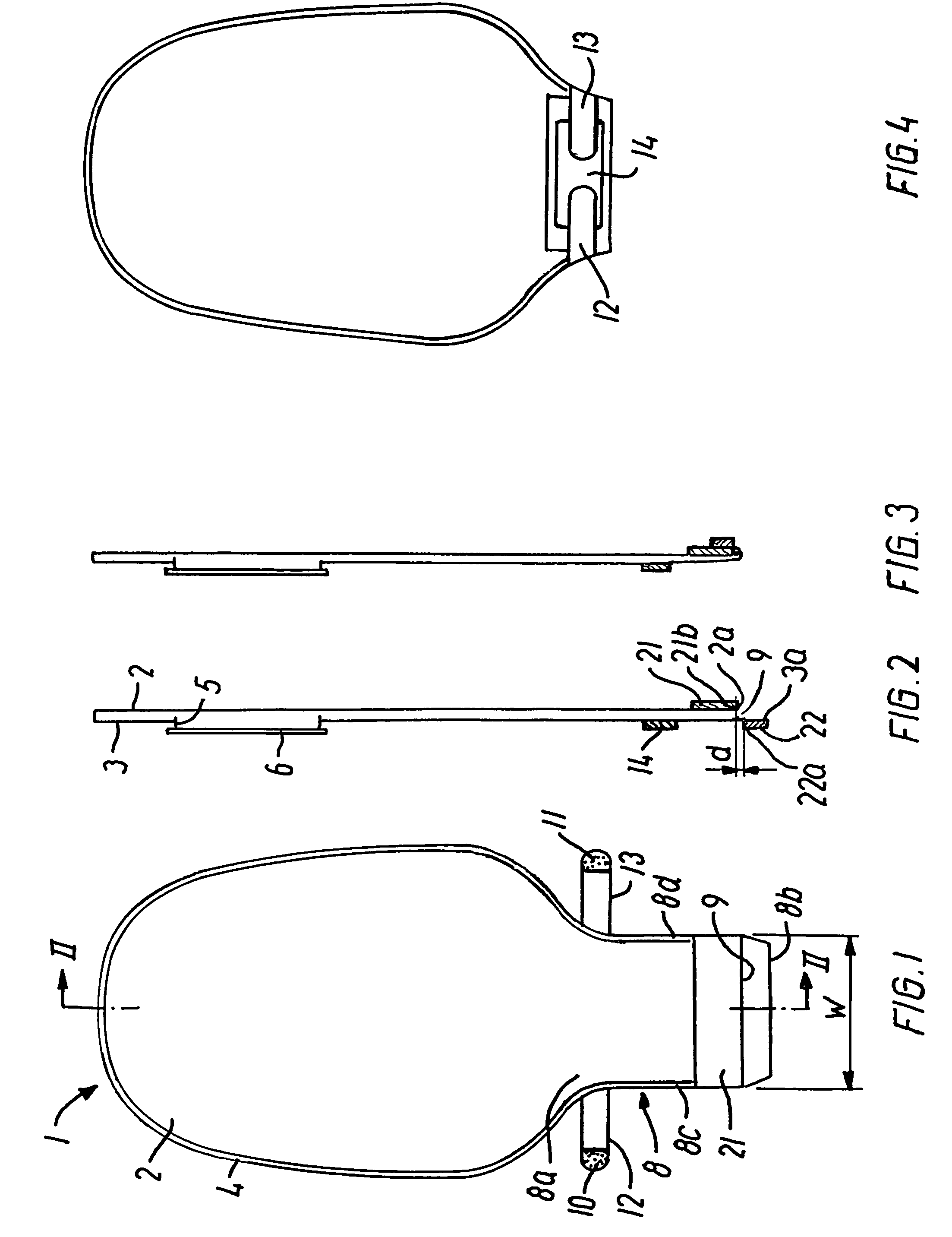
[0027]In FIGS. 2 and 3 some sectional areas are indicated by fully drawn lines in order not to impede the clear reading of the drawings.

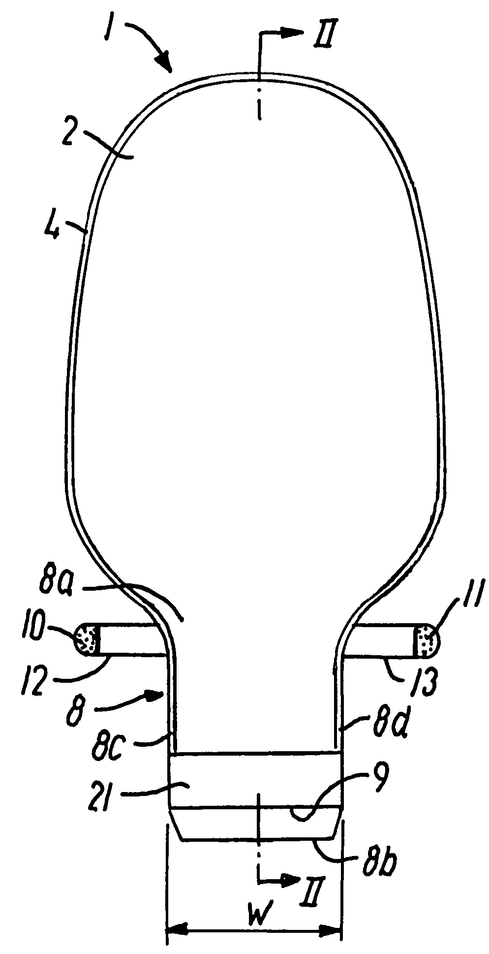
[0028]The collecting bag shown in the drawings is designed as an ostomy bag of a generally known and common type and comprises a bag member 1 formed by first and second film blanks 2,3 which are joined along their edges by means of a seam 4 made by welding or in any other convenient manner. The film blanks may be made from a suitable flexible plastic sheet or foil material that p...


PUM


Abstract

The collecting bag has a bag member formed by a first and a second film blank, and a discharge portion that is foldable and unfoldable to bring the discharge portion from an open unfolded condition to a closed folded condition and vice versa. A first plate member is positioned on the first film blank and a second plate member is positioned on an extension of the second film blank Each plate member is formed from a relatively stiff material, and the distance between the distal edge of the first plate member and the proximal edge of the second plate member is smaller than the thickness of the first plate member. When folding the discharge portion, the distal edge of the first plate member acts as a pivot, and a stretching effect is created on the second film blank to effectively seal the discharge opening without deformation of the plate members.

Description

CROSS-REFERENCE TO RELATED APPLICATIONS[0001]The present application claims the benefit of priority from Danish Patent Application No. PA 2002 01474 filed on Oct. 2, 2002.BACKGROUND OF THE INVENTION[0002]The invention relates to a collecting bag for human body wastes, comprising a bag member and a discharge portion defining a longitudinal direction. The discharge portion is foldable and unfoldable by at least one folding in said longitudinal direction between to bring the discharge portion from an open unfolded condition to a closed folded condition and vice versa, and a locking device is provided at the discharge portion for locking the bag in said closed folded condition of the discharge portion.[0003]This type of drainable collecting bags are often used as ostomy bags. In the case of ileostomy patients and colostomy patients with uncontrolled release of faeces of a more or less fluid consistence, the collecting bag has to be emptied rather frequently, and the closure device thus ...

Claims


Application Information

Patent Timeline
Patent Type & Authority Patents(United States)
IPC IPC(8): A61M1/00A61F5/44
CPCA61F5/4407
Inventor HANSEN, SORENPOULSEN, LARS BO
Owner COLOPLAST AS
Why Eureka
Try Eureka