Leakage current protection plug and interrupt protection plug contact spring structure

a technology of leakage current protection and interrupt protection, which is applied in the direction of emergency protection arrangements for limiting excess voltage/current, earth fault current switch operation, coupling device connection, etc., can solve the problems of easy danger of application for appliances, easy to be easily prone to danger for their application, and complex production process. , to achieve the effect of simple production process, stable and reliable performance and low cos

Active Publication Date: 2012-07-03
LUEN MING ELECTRIC WORKS
View PDF9 Cites 2 Cited by
  • Summary
  • Abstract
  • Description
  • Claims
  • Application Information

AI Technical Summary

Benefits of technology

[0004]One object of the present invention is to provide a leakage current protection plug with merits of simple producing process, stable and reliable performance as well as lower cost.
[0005]The other object of the present invention is to provide an interrupt protection plug contact spring structure with more stable performance that maintains continuous spring force between the mutually contacted conductive contacts.
[0007]Once a leakage current occurs, the ZCT, upon sensing an unbalance current on the power supply cord, triggers the control circuits to drive the winding assemble, the iron core moves towards the hole within the winding assemble, the slot on the reset button gets out from the L plate of the iron core, and the moving contacts are separated from the copper legs; in this way, the appliance is well protected against the leakage current.
[0010]Beneficial effects: the leakage current protection plug of the invention is in a simple structure because it makes the ZCT simplified and the winding assemble coordinately and controls the on and off of the power supply with a spring snap-latch mechanism, so that the cost for producing such a plug is also substantially reduced while the performance becomes more stable.
[0012]Further, the legs of the interrupt protection plug contact spring structure can be fabricated as folded hollow copper sheets with a thickness of 0.5 mm and exterior size of 1.5 mm; such a thin copper leg not only maintains enough pressing force between the leg and the socket, but also reduces the weight of the copper sheets so as to lower cost of the material.
[0013]Beneficial effects: in the case the interrupt protection plug contact spring structure of the invention is working, once the reset button outside the housing is pushed by a hand, the reset button moves downwards through overcoming the pressure from the push-out spring, then the slot of the reset button will engage with the L plate, then, the L plate comes into connection with the iron core and squeezes the bouncing spring till it comes into the slot of the reset button; meanwhile, the actuator and the reset button are positioned mutually stationary to each other; then the reset button is loosened, the actuators, together with the reset button, move upwards under the bouncing force from the push-out spring, so does the moving contact connected fixedly with the actuators, and then the moving contact comes into contact with the fixed contact, so that the circuit of the interrupt protection plug turns on entirely; once a break occurs, the winding assemble generates an instantaneous, relatively high magnetic attracting force, then the iron core moves inwards upon overcoming pressure from the bounce spring, while then the L plate within in the actuators gets out from the slot then moves downwards under the bouncing force from the press-in spring, which thus brings the moving contact apart from the fixed contact; in this way, the circuit is cut off so as to provide protection to the circuit once a break occurs. Further, in the case the power supply is on, the actuator would, under the spring force from the push-out spring, continuously produce proper bouncing force against the fixed contact, thus the interrupt protection plug contact spring structure can ensure sufficient tightness between the moving contact and the fixed contact, so that there is hardly any chance for ill contact because of gap coming up due to use for a long time. Additionally, it is not necessary to make the moving contact open under force of the spring itself, since the contacts are brought apart from each other under the spring force from the press-in spring, thus the moving contacts is set free from break and from inability to bounce back or the like caused due to fatigue of metal. Furthermore, the legs of the interrupt protection plug contact spring structure can be fabricated as folded hollow copper sheets with a thickness of 0.5 mm and exterior size of 1.5 mm, while such a design will not affect the closeness between the legs of said plug and the sockets as well as rigidity of the copper legs. Instead, along with reduction in consumption of the expensive copper materials, both the weight and cost of the legs are effectively lowered finally.

Problems solved by technology

However, since these appliances usually work at a voltage that is prone to cause danger to people, thus a need to enhance protection against leakage current of the appliances gains particularly more and more concerns.
The ordinary households though are equipped with leakage current interrupters which can provide protection against leakage current, these leakage current interrupters are usually disposed at the master switchboard of houses; a single room usually has a relatively high power consumption, thus the leakage current interrupters disposed at the master switchboard is usually set up with a much high safety current level, which thence cannot provide an ideal protection against leakage current.
With consideration to such a concern, people begin to devise leakage current protection device applied on individual appliance for the sake of enhancing the interrupt protection once a leakage current occurs to an appliance; in the United States, it is enforced to add leakage current protection devices on some appliances, such as hair dryer and appliances used in bathroom, because these appliances are easily prone to danger for their application in the damp and wet environment.
At present, the leakage current protection devices applicable for the appliances are, generally speaking, leakage current protection plugs; however, the common leakage current protection plugs in the market are usually made in complicated structures, whose producing process is noticeably complex.
Namely, the leakage current protection plugs are necessarily subject to shortcomings of lower production, high cost, fragile structure and lower stability in performance.
However, in the case the plug is applied to a interrupt device with great high current, the spring cantilever has to be fabricated much thicker so as to lower the temperature rise of the spring itself, but once the spring cantilever becomes thicker, the spring force of the spring cantilever will be affected tremendously.
Consequently, the open-to-close durability of the spring cantilever becomes shorter under a bad spring force; accordingly, the durability of the plug will be affected too.

Method used


Image

  • Leakage current protection plug and interrupt protection plug contact spring structure
  • Leakage current protection plug and interrupt protection plug contact spring structure
  • Leakage current protection plug and interrupt protection plug contact spring structure

Examples


Embodiment Construction

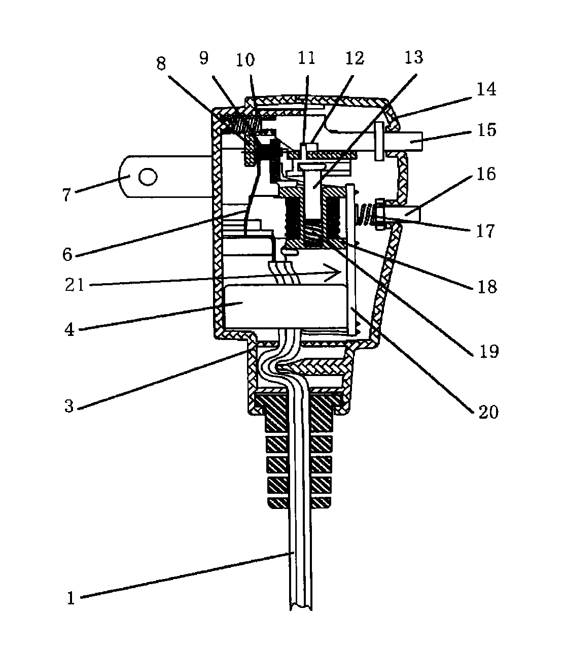
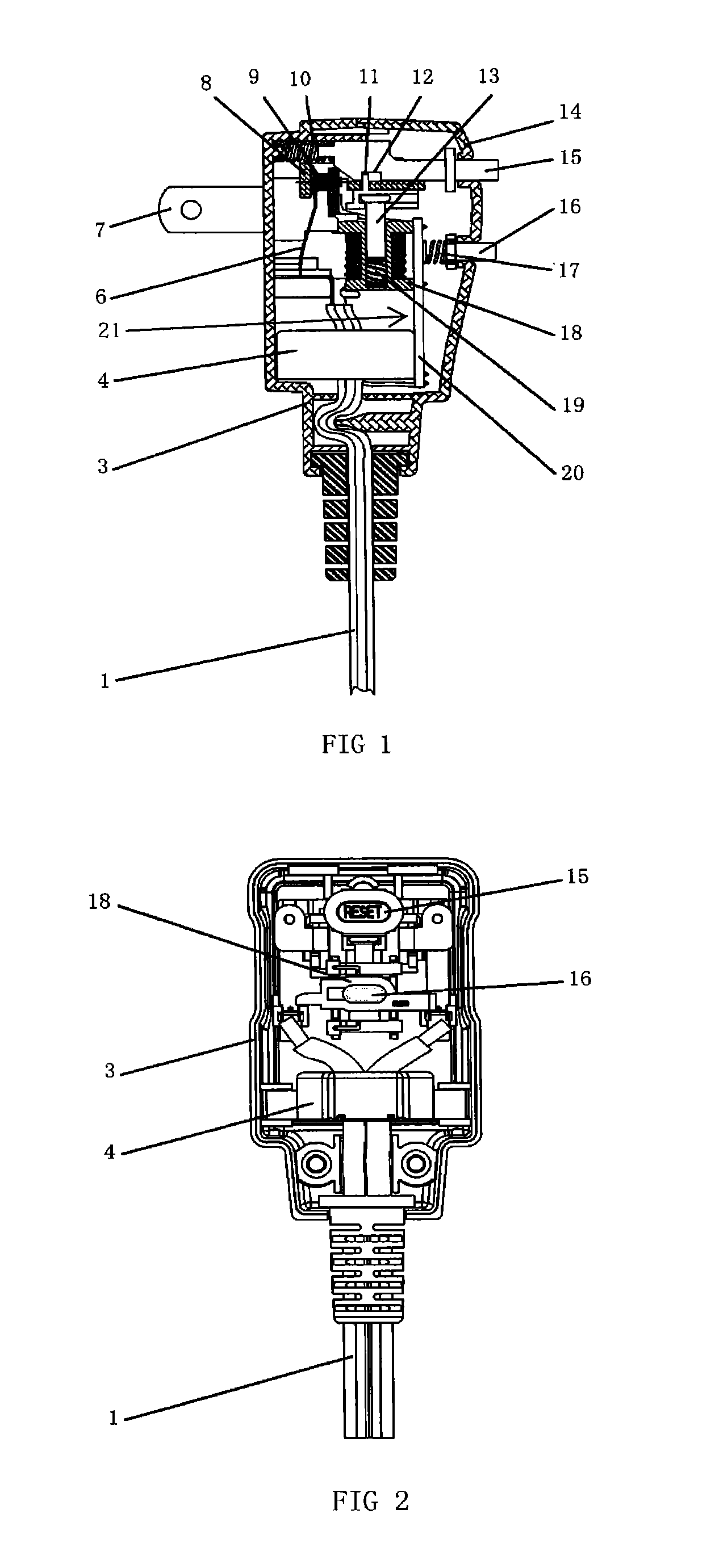
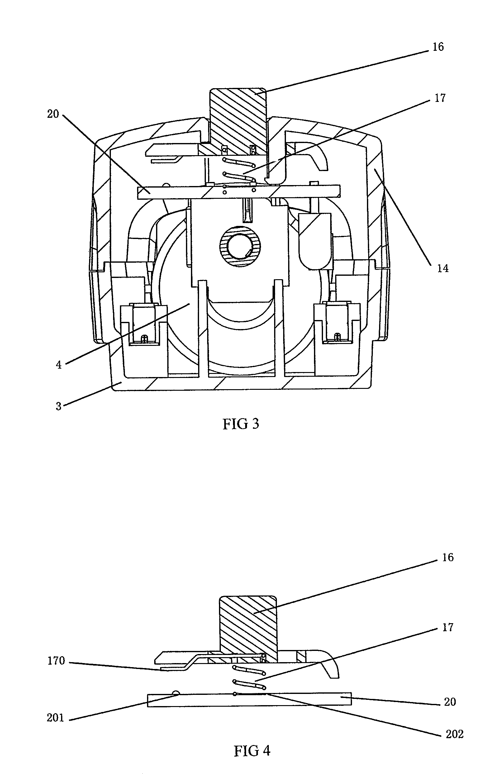
[0023]Turn to FIG. 1 and FIG. 2 that show the structural figures for a specific embodiment for the present invention. The leakage current protection plug of the invention, which is applicable for protecting appliances against leakage current danger, comprises a plug housing, a power supply cord 1, two copper legs 7 embedded within the plug housing, a leakage current protection device, wherein the copper legs 7 are connected to the socket housing fixedly at the front part of the socket; the leakage current protection device comprises two main moving arm 6, a reset button 15, a winding assemble 18, an iron core 13, a circuit board assemble 20 and an ZCT 4.

[0024]In this embodiment, the plug housing is composed of an upper housing 14 and a lower housing 3; the two main moving arm 6 are conductive metal reeds with good resilience, and the respective two moving arms 6 are arranged correspondingly and connected fixedly with the power supply cord 1, two copper legs 7 at an end within the in...


PUM


Abstract

A leakage current protection plug includes a plug housing, a power supply cord, two copper legs embedded within the plug housing, a leakage current protection device composed of two main moving contacts. A reset button presses the moving contacts to contact the two copper legs, a winding assemble, an iron core, a circuit board assemble, an ZCT. Ends of moving contacts are arranged with contacts that conduct individually with the two copper legs upon coming into contact; the power supply cord, through the ZCT, is connected with the moving contacts; the output of the ZCT is connected with the input of the amplification circuit on the circuit board, while the output of the amplification circuit is connected with the winding assemble.

Description

TECHNICAL FIELD[0001]The present invention relates a power supply plug, in particular, a leakage current protection plug able to provide protection against leakage current. This invention further relates to a current interrupter protection plug contact spring structure whose contact applies a spring structure to enhance contact stability but to reduce resistance.BACKGROUND ART[0002]Nowadays, various appliances, especially, domestic appliances and office electrical apparatus, become more and more indispensable for our daily life. However, since these appliances usually work at a voltage that is prone to cause danger to people, thus a need to enhance protection against leakage current of the appliances gains particularly more and more concerns. The ordinary households though are equipped with leakage current interrupters which can provide protection against leakage current, these leakage current interrupters are usually disposed at the master switchboard of houses; a single room usual...

Claims


Application Information

Patent Timeline
Patent Type & Authority Patents(United States)
IPC IPC(8): H02H3/16
CPCH01H83/04H01R13/7135H01R13/6658H01R24/28H01R2103/00
Inventor LI, HIN YEUNG
Owner LUEN MING ELECTRIC WORKS
Why Eureka
Try Eureka