Method for preventing erroneous mounting of mounting part on main body device, mounting part and battery pack used for this

a technology of mounting parts and battery packs, which is applied in the direction of batteries, primary cell maintenance/service, sustainable manufacturing/processing, etc., can solve the problems of erroneous loading of battery packs on the main, malfunctioning and damage of the main body side apparatus, and high possibility, so as to prevent erroneous loading of battery packs

Active Publication Date: 2007-05-29
SONY CORP
View PDF35 Cites 17 Cited by
  • Summary
  • Abstract
  • Description
  • Claims
  • Application Information

AI Technical Summary

Benefits of technology

[0013]Therefore, an object of the present invention is to surely prevent electric disturbance from occurring to the main side body apparatus and / or component-to-be-loaded by preventing terminals from contacting with each other even when a similar component-to-be-loaded is erroneously loaded on the main side body apparatus by any chance.
[0016]Accordingly, in the method for preventing erroneous loading of the component-to-be-loaded on the main body side apparatus and the component-to-be-loaded according to the present invention, in case the component-to-be-loaded that can not be loaded under regular circumstances is erroneously loaded on the main body side apparatus, since the discriminating tab and the blocking portion are provided in the vicinity of the terminals, it is possible to prevent the terminals from contacting with each other as well as to surely prevent electrical disturbance of the main body side apparatus and / or the component-to-be-loaded.
[0018]Therefore, according to the battery pack of the present invention, since the form seen from the sliding direction is not symmetry at multiple points, it is possible to specify unique orientation of the battery pack with respect to the battery loading portion on the side of the electronic apparatus. As a result, it is impossible to insert the battery pack into the battery loading portion when the battery pack is in different orientation from the regular orientation, with the result that the erroneous loading of the battery pack can be prevented.
[0019]Further, such being the case, since the battery pack is inserted into the battery loading portion with the orientation thereof being in the regular orientation, it is possible to prevent the trouble in which a terminal on the side of the electronic apparatus and a wrong terminal themselves are brought into contact with each other.

Problems solved by technology

However, as mentioned above, in a conventional main body side apparatus and component-to-be-loaded provided with the concave engaging portion and the convex engaging portion, there has been a problem in which terminals of the two are brought into contact with each other while the component-to-be-loaded is in the state of not completely loaded on the main body side apparatus, that is, in the halfway stage of being loaded.
Then, should a battery pack with different capacity, for example, be loaded on the main body side apparatus, there flows a large amount of current, which incurs the problem such that the main body side apparatus malfunctions and is damaged.
However, when the concave engaging portion and the convex engaging portion are reduced in form and in size as well, the possibility is very high that component-to-be-loaded that should not be capable of being loaded under regular circumstances are erroneously loaded on the main body side apparatus due to changes in form and deformation.
In case erroneous loading is committed, there is a high possibility that terminals themselves are brought into contact with each other to thereby incur a problem that leads to some kinds of troubles.

Method used


Image

  • Method for preventing erroneous mounting of mounting part on main body device, mounting part and battery pack used for this
  • Method for preventing erroneous mounting of mounting part on main body device, mounting part and battery pack used for this
  • Method for preventing erroneous mounting of mounting part on main body device, mounting part and battery pack used for this

Examples


Embodiment Construction

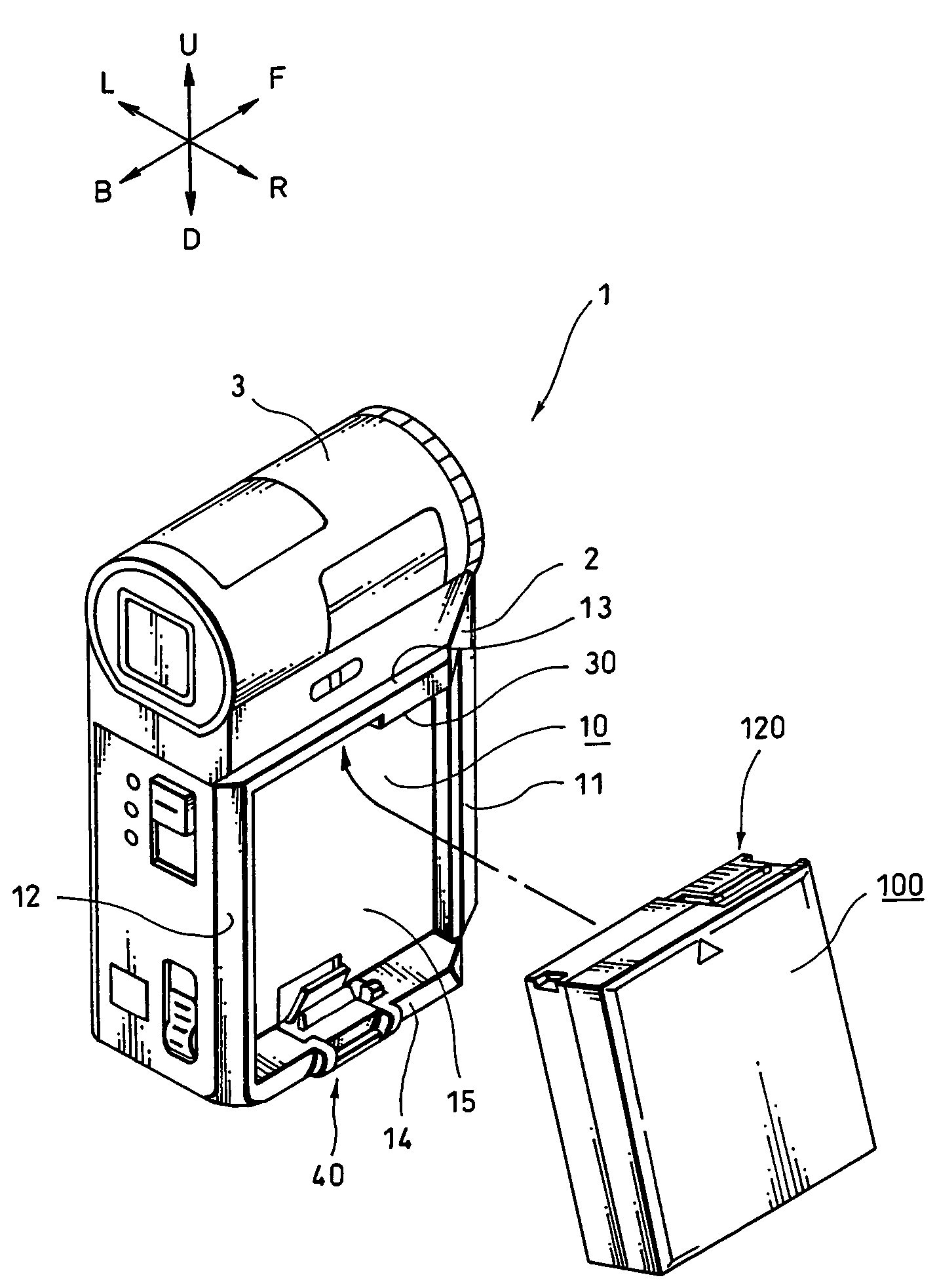
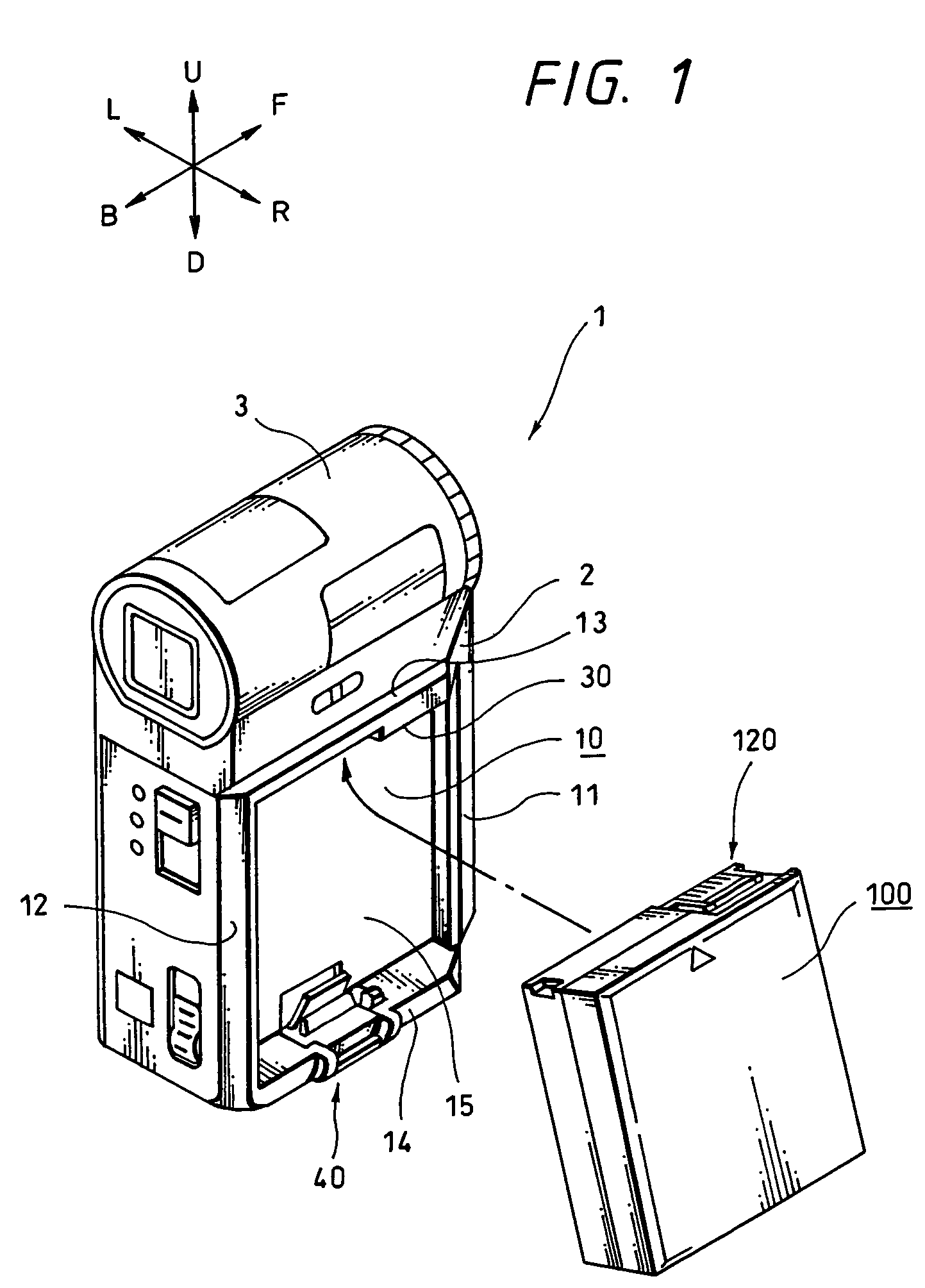
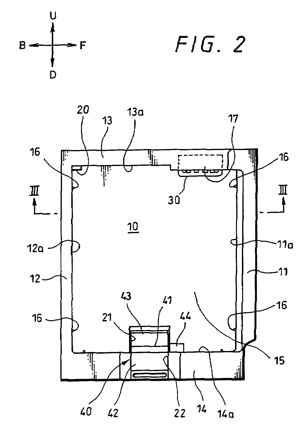
[0071]Hereinafter, a method for preventing a component-to-be-loaded from being erroneously loaded on a main body side apparatus, a component-to-be-loaded and a battery pack will be explained in detail according to embodiments illustrated in the attached drawings.

[0072]In addition, the embodiments shown in the drawings are such that the present invention is applied to the structure of how the battery pack is loaded in a video camera, wherein ┌video camera┘ corresponds to ┌main body side apparatus┘ described in the scope of claim, and ┌battery pack┘ corresponds to ┌component-to-be-loaded┘ described in the scope of claim, respectively. In addition, ┌video light┘, ┌battery charger┘ to be mentioned later on correspond to ┌main body side apparatus┘, and ┌dry cell pack┘ corresponds to ┌component-to-be-loaded┘ described in the scope of claim, respectively.

[0073]Further, a video camera to be explained in the following is a camera of the type which has a lens body tube positioned at its upper...


PUM

PropertyMeasurementUnit
thicknessaaaaaaaaaa
thicknessaaaaaaaaaa
open circuit voltageaaaaaaaaaa

Abstract

Contact of terminals of a component to be loaded on a device and terminals on the device are avoided, even if the component is similar to, but differs from, a component intended to be loaded on that device. A discriminating tab is provided in the vicinity of the component terminals and a blocking portion is provided in the vicinity of the device terminals. The discriminating tab and blocking portion are relatively positioned to provide concave and convex interference or engagement with each other, either to block connection of the component terminal with the device terminal because of interference if the component is not permitted to be loaded on the device, or to permit connection of the component terminal with the device terminal because of engagement.

Description

TECHNICAL FIELD[0001]The present invention relates to a method for preventing erroneous loading of a component-to-be-loaded that has a terminal aimed for electric contact, a component-to-be-loaded and a battery pack.BACKGROUND ART[0002]As a component-to-be-loaded that is aimed for electric contact with a main body apparatus, there is provided a battery pack that is loaded on a video camera.[0003]Such a battery pack can be loaded on a video light, a battery charger and the like other than the video camera, and is in need of aiming for electric contact with these appliances all of which are provided with a terminal of the same form.[0004]Additionally, there are plural-types of batteries based on the difference of capacity and further, as a component-to-be-loaded having a terminal of the same form that is similar to the battery pack, there are, for example, a dry cell pack, a DC plate and the like. By the way, the DC plate is a component-to-be-loaded that has an outer form like the bat...

Claims


Application Information

Patent Timeline
Patent Type & Authority Patents(United States)
IPC IPC(8): H01M10/38H01M2/10H01M6/42H01M6/50H01M10/48H01M50/209H01M50/296H01M50/528H01M50/588H04N5/225
CPCH01M2/1066H01M2/22H01M2/342H01M10/486H01M2/02H01M2/0217H01M2/0202H01M2/34H01M2/20H04N5/2251H01M2200/106Y10T29/49826Y02E60/10H01M50/209H01M50/528H01M50/597Y02P70/50H01M50/588H01M50/296H04N23/50H01M50/103H01M2220/30
Inventor TAKESHITA, TOSHIOEBINE, NOBUHITOKATSUNO, YOSHIYUKITASHIRO, KEI
Owner SONY CORP
Why Eureka
Try Eureka